
Instruction Manual

A-101-3
Modular Vactrol Phaser
System A - 100
doepfer
6
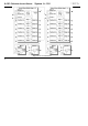
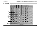
Controls:
1 Level: attenuator for audio input !
2 CV: attenuator for CV input "
3 Shift: manual phase shift
4 Mix: mixing ratio between original and phase
shifted signal
5 Pol.: polarizer control
6 Shift: LED display for pase shift
(= brightness of the LEDs inside the
vactrols)
Inputs / Outputs:
! Audio In: Audio input
" CV In: Control voltage input
§ Shifted Audio In: Mixer input for phase shifted si-
gnal (normalled to output stage
6)
$ Mixed Audio Out: Mixer output (= phase shifter
audio output)
% Polarizer In: Polarizer input (two sockets,
one is normalled to output stage
6)
& Polarizer Out: Polarizer output
/ Feedback In: Feedback inputs (6x, feedback
In 1 is normalled to polarizer
output)
( Stage Out: Phase shifter outputs (6x)
Only the elements of one of the two identical phase shift units is specified. The second unit is identical with these
exceptions:
• "Audio In 7-12" is normalled to output stage 6 (i.e. all 12 stages are daisy-chained - even between stage 6 and
stage 7 - provided that no plug is inserted into socket "Audio In In 7-12")
• "CV In 7-12" is normalled to socket "CV In 1-6" (i.e. same CV for both units provided that no plug is inserted
into socket "CV In 7-12")