
Owner manual


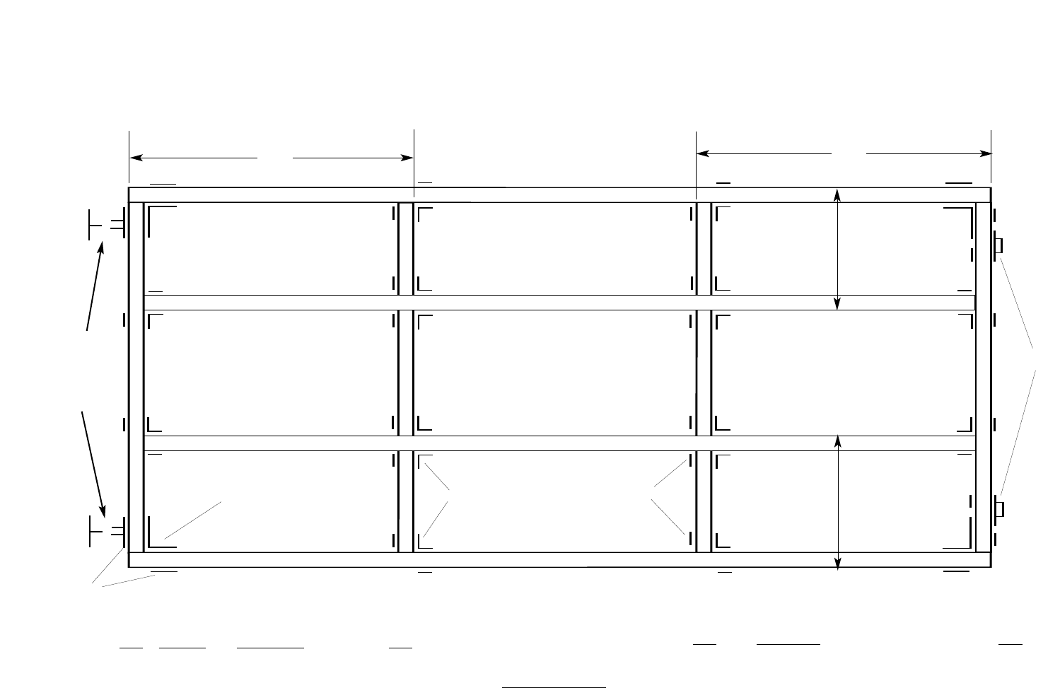
Typical Joint Configuration
DOCK HARDWARE INCLUDED
REF Part# Description QTY
A 93-122-F Backer Plate 6
B 92-104-F Inside Corner 4
C 99-002-F Joist Corner 16
D 99-006-F Washer Plate 28
E 99-013-F
Anchor Chain Retainer
2
Additional Hardware required for modular attachment
to an additional DOCK-2Go Section
99-011-F Female “T” Connector 2
99-012-F
Male “T” Connector 2
96-1
1
1-F
Connector Pin
2
93-122-F Backer Plate 4
B
C
D
E
A
T
OOLS REQUIRED
Hammer
Drill
5/8” Drill Bit
Socket and wrench Set
24”
a
a
a
a
b
b
c
c
c
c
d
d
d
d
d
d
d
d
e
e
e
e
b
b
24”
48”
48”
LUMBER REQUIRED
REF Description QTY
a 2” x 6” x 12’ Outside Stringers 2
b 2” x 6” x 69” Ends Stringers 2
c 2” x 6” x 141” Short Cross Stringers
2
d 2” x 6” x 21” Inside Blocker
4
e 2” x 6” x 24” Inside Blocker 2
f 2” x 6” x 6’
Deck Boards
24
Optional placement
of connectors for
modular assembly
(replaces backer
plates in these posi-
tions
Part# 85-205-F
}