
Manual


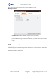
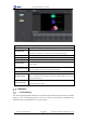

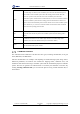


Table Of Contents
- 1. Updates
- 2. Product Introduction
- 3. Software Interface
- 3.1 Welcome Page
- 3.2 Home Page
- 3.3 Menu
- 3.4 Control Toolbar
- 3.5 Tool Box
- 3.6 Result Display
- 3.7 Flow Management
- 3.8 Camera Management
- 3.9 Controller Management
- 3.10 Global Variables
- 3.11 Communication Management
- 3.12 Global Trigger
- 3.13 Global Script
- 3.14 Operation Interface
- 3.15 Data Queue
- 3.16 Flow Time
- 3.17 Dobot Panel
- 4. Vision Tools
- 4.1 Acquisition
- 4.2 Location
- 4.2.1 Feature Match
- 4.2.2 Greyscale Match
- 4.2.3 Mark Location
- 4.2.4 Circle Search
- 4.2.5 Line Search
- 4.2.6 Blob Analysis
- 4.2.7 Caliper
- 4.2.8 Edge Search
- 4.2.9 Position Correction
- 4.2.10 Rect Search
- 4.2.11 Peak Search
- 4.2.12 Edge Intersection
- 4.2.13 Parallel Lines Search
- 4.2.14 Quadrilateral Search
- 4.2.15 Line Group Search
- 4.2.16 Multi-line Search
- 4.2.17 Blob Label Analysis
- 4.2.18 Path Extraction
- 4.2.19 Find Angle Bisector
- 4.2.20 Find Median Line
- 4.2.21 Calculate Parallel Lines
- 4.2.22 Find Vertical Line
- 4.3 Measurement
- 4.4 Image Generation
- 4.5 Recognition
- 4.6 Deep Learning
- 4.7 Calibration
- 4.8 Calculation
- 4.9 Image Processing
- 4.9.1 Image Combination
- 4.9.2 Image Morphology
- 4.9.3 Image Binarization
- 4.9.4 Image Filter
- 4.9.5 Image Enhancement
- 4.9.6 Image Computing
- 4.9.7 Distortion Correction
- 4.9.8 Image Clarity
- 4.9.9 Image Fixture
- 4.9.10 Shade Correction
- 4.9.11 Affine Transformation
- 4.9.12 Ring Expansion
- 4.9.13 Copy and Fill
- 4.9.14 Frame Mean
- 4.9.15 Image Normalization
- 4.9.16 Image Correction
- 4.9.17 Geometric Transformation
- 4.9.18 Image Stitch
- 4.9.19 Multiple Images Fusion
- 4.10 Color Processing
- 4.11 Defect Detection
- 4.11.1 OCV
- 4.11.2 Arc Edge Defect Detection
- 4.11.3 Linear Edge Defect Detection
- 4.11.4 Arc-Pair Defect Detection
- 4.11.5 Line-Pair Defect Detection
- 4.11.6 Edge Group Defect Detection
- 4.11.7 Edge Pair Group Defect Detection
- 4.11.8 Edge Model Defect Detection
- 4.11.9 Edge Pair Model Defect Detection
- 4.11.10 Defect Contrast
- 4.12 Logic Tools
- 4.13 Communication
- 4.14 Dobot Magician Tools
- 5. Cases
- 6. Dobot Magician Demo

DobotVisionStudio User Guide
Issue V4.1.2 (2022-06-08) User Guide Copyright © Yuejiang Technology Co., Ltd.
162
⚫ Check whether the calibration type in the basic parameters is set correctly.
⚫ Check whether the parameter setting is reasonable. For checkerboard calibration,
check whether the gray contrast is high. If so, you can change the sub-pixel window
from adaptive to the set value, and set the window size to about checkerboard pixel
width/10.
⚫ For the round dot matrix calibration board, check whether the round dot type is set
correctly, whether the dot roundness threshold is too high, and whether the edge
extraction threshold is unreasonable.
N-Point Calibration
The calibration is mainly used to determine the conversion relations between the camera coordinate
system and the robot arm coordinate system. The N-point calibration realizes the conversion
between the camera coordinate system and the executing structure coordinate system and generates
calibration file via N-point pixel coordinate and physical coordinate. The N needs to be larger than
or equal to 4.
In the actual situation, there are mainly two calibration methods, including upper camera capture
and lower camera alignment, as shown below.
The recommended calibration solution is shown below. The branch module is used to determine
whether feature matching is successful or not. If it is successful, the flow enters N-point calibration.
Otherwise, format a specific character and sent it out to feed back the matching results.