
Manual


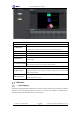


Table Of Contents
- 1. Updates
- 2. Product Introduction
- 3. Software Interface
- 3.1 Welcome Page
- 3.2 Home Page
- 3.3 Menu
- 3.4 Control Toolbar
- 3.5 Tool Box
- 3.6 Result Display
- 3.7 Flow Management
- 3.8 Camera Management
- 3.9 Controller Management
- 3.10 Global Variables
- 3.11 Communication Management
- 3.12 Global Trigger
- 3.13 Global Script
- 3.14 Operation Interface
- 3.15 Data Queue
- 3.16 Flow Time
- 3.17 Dobot Panel
- 4. Vision Tools
- 4.1 Acquisition
- 4.2 Location
- 4.2.1 Feature Match
- 4.2.2 Greyscale Match
- 4.2.3 Mark Location
- 4.2.4 Circle Search
- 4.2.5 Line Search
- 4.2.6 Blob Analysis
- 4.2.7 Caliper
- 4.2.8 Edge Search
- 4.2.9 Position Correction
- 4.2.10 Rect Search
- 4.2.11 Peak Search
- 4.2.12 Edge Intersection
- 4.2.13 Parallel Lines Search
- 4.2.14 Quadrilateral Search
- 4.2.15 Line Group Search
- 4.2.16 Multi-line Search
- 4.2.17 Blob Label Analysis
- 4.2.18 Path Extraction
- 4.2.19 Find Angle Bisector
- 4.2.20 Find Median Line
- 4.2.21 Calculate Parallel Lines
- 4.2.22 Find Vertical Line
- 4.3 Measurement
- 4.4 Image Generation
- 4.5 Recognition
- 4.6 Deep Learning
- 4.7 Calibration
- 4.8 Calculation
- 4.9 Image Processing
- 4.9.1 Image Combination
- 4.9.2 Image Morphology
- 4.9.3 Image Binarization
- 4.9.4 Image Filter
- 4.9.5 Image Enhancement
- 4.9.6 Image Computing
- 4.9.7 Distortion Correction
- 4.9.8 Image Clarity
- 4.9.9 Image Fixture
- 4.9.10 Shade Correction
- 4.9.11 Affine Transformation
- 4.9.12 Ring Expansion
- 4.9.13 Copy and Fill
- 4.9.14 Frame Mean
- 4.9.15 Image Normalization
- 4.9.16 Image Correction
- 4.9.17 Geometric Transformation
- 4.9.18 Image Stitch
- 4.9.19 Multiple Images Fusion
- 4.10 Color Processing
- 4.11 Defect Detection
- 4.11.1 OCV
- 4.11.2 Arc Edge Defect Detection
- 4.11.3 Linear Edge Defect Detection
- 4.11.4 Arc-Pair Defect Detection
- 4.11.5 Line-Pair Defect Detection
- 4.11.6 Edge Group Defect Detection
- 4.11.7 Edge Pair Group Defect Detection
- 4.11.8 Edge Model Defect Detection
- 4.11.9 Edge Pair Model Defect Detection
- 4.11.10 Defect Contrast
- 4.12 Logic Tools
- 4.13 Communication
- 4.14 Dobot Magician Tools
- 5. Cases
- 6. Dobot Magician Demo

DobotVisionStudio User Guide
Issue V4.1.2 (2022-06-08) User Guide Copyright © Yuejiang Technology Co., Ltd.
161
translation. The three parameters correspond to perspective transformation, affine transformation
and similarity transformation respectively.
• Grayscale Contrast: it refers to the min. value of contrast between adjacent black-and-
white squares in a checkerboard image, it is recommended to use default value.
• Subpixel Window: this parameter indicates whether to adaptively calculate the window
size of corner sub-pixel accuracy. When each checkerboard grid accounts for more pixels, this value
can be increased appropriately. It is recommended to use the default value.
• Set Window Size: it refers to the size of subpixel window that user sets. The width of each
checkerboard pixel of the calibration board can be adjusted as /10.
• Weighting Function: you can select least squares, Huber, and Tukey algorithm functions.
It is recommended to use default parameter.
• Weighting Coefficient: it is the parameter setting item when Tukey or Huber weight
function is selected. It is the clipping factor of the corresponding method and recommended to use
the default value.
Output Results:
• Calibration Error: it is the calibration parameters by calculation. The physical coordinates
of the extracted calibration board feature points (such as checkerboard corner points or circle center
of circle calibration board) are mapped back to the image coordinates system, which is the average
value of the distance from the actual image coordinates.
• Scale: the unit length in the world coordinate system corresponds to the number of pixels
in the image coordinate system.
• Pixel Accuracy: the size in the physical coordinate system corresponding to a single pixel.
• Calibration Point Quantity: number of extracted calibration plate feature points.
• Translation X/Y: it is the calibration parameters by calculation. The origin of the world
coordinate system is mapped to image coordinates system, and obtain the coordinate X/Y.
• Rotation: the rotation angle (unit: radians) of the world coordinate system relative to the
image coordinate system. When rotating θ is positive, and after the X-axis of the world coordinate
system rotates counterclockwise θ, its X-axis is consistent with the X-axis direction of the image
coordinate system θ. When it is negative, and after the X-axis of the world coordinate system rotates
clockwise θ, its X-axis is consistent with the X-axis direction of the image coordinate system.
• Chamfer: difference between Y-axis rotation angle and X-axis rotation angle of world
coordinate system (unit: radians).
• Aspect Ratio: the ratio of Y-axis scaling to X-axis scaling in the world coordinate system.
NOTICE
When failing to use the calibration tool, you need to adjust the parameters. The common
debugging steps are as follows:
⚫ Check whether the input image is a calibration board image.