
Manual


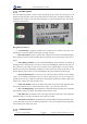


Table Of Contents
- 1. Updates
- 2. Product Introduction
- 3. Software Interface
- 3.1 Welcome Page
- 3.2 Home Page
- 3.3 Menu
- 3.4 Control Toolbar
- 3.5 Tool Box
- 3.6 Result Display
- 3.7 Flow Management
- 3.8 Camera Management
- 3.9 Controller Management
- 3.10 Global Variables
- 3.11 Communication Management
- 3.12 Global Trigger
- 3.13 Global Script
- 3.14 Operation Interface
- 3.15 Data Queue
- 3.16 Flow Time
- 3.17 Dobot Panel
- 4. Vision Tools
- 4.1 Acquisition
- 4.2 Location
- 4.2.1 Feature Match
- 4.2.2 Greyscale Match
- 4.2.3 Mark Location
- 4.2.4 Circle Search
- 4.2.5 Line Search
- 4.2.6 Blob Analysis
- 4.2.7 Caliper
- 4.2.8 Edge Search
- 4.2.9 Position Correction
- 4.2.10 Rect Search
- 4.2.11 Peak Search
- 4.2.12 Edge Intersection
- 4.2.13 Parallel Lines Search
- 4.2.14 Quadrilateral Search
- 4.2.15 Line Group Search
- 4.2.16 Multi-line Search
- 4.2.17 Blob Label Analysis
- 4.2.18 Path Extraction
- 4.2.19 Find Angle Bisector
- 4.2.20 Find Median Line
- 4.2.21 Calculate Parallel Lines
- 4.2.22 Find Vertical Line
- 4.3 Measurement
- 4.4 Image Generation
- 4.5 Recognition
- 4.6 Deep Learning
- 4.7 Calibration
- 4.8 Calculation
- 4.9 Image Processing
- 4.9.1 Image Combination
- 4.9.2 Image Morphology
- 4.9.3 Image Binarization
- 4.9.4 Image Filter
- 4.9.5 Image Enhancement
- 4.9.6 Image Computing
- 4.9.7 Distortion Correction
- 4.9.8 Image Clarity
- 4.9.9 Image Fixture
- 4.9.10 Shade Correction
- 4.9.11 Affine Transformation
- 4.9.12 Ring Expansion
- 4.9.13 Copy and Fill
- 4.9.14 Frame Mean
- 4.9.15 Image Normalization
- 4.9.16 Image Correction
- 4.9.17 Geometric Transformation
- 4.9.18 Image Stitch
- 4.9.19 Multiple Images Fusion
- 4.10 Color Processing
- 4.11 Defect Detection
- 4.11.1 OCV
- 4.11.2 Arc Edge Defect Detection
- 4.11.3 Linear Edge Defect Detection
- 4.11.4 Arc-Pair Defect Detection
- 4.11.5 Line-Pair Defect Detection
- 4.11.6 Edge Group Defect Detection
- 4.11.7 Edge Pair Group Defect Detection
- 4.11.8 Edge Model Defect Detection
- 4.11.9 Edge Pair Model Defect Detection
- 4.11.10 Defect Contrast
- 4.12 Logic Tools
- 4.13 Communication
- 4.14 Dobot Magician Tools
- 5. Cases
- 6. Dobot Magician Demo

DobotVisionStudio User Guide
Issue V4.1.2 (2022-06-08) User Guide Copyright © Yuejiang Technology Co., Ltd.
138
BCR Recognition
The tool of BCR recognition is used to locate and identify the bar code in the specified area, and
tolerate the target barcode to rotate at any angle and tilt at a certain angle. It supports CODE39 code,
CODE128 code, Codabar code, EAN code, alternating 25 code and CODE93 code. The specific
operation is shown below.
Recognition Parameters:
• Code Enabling: it supports CODE39 code, CODE128 code, Codabar code, EAN code,
alternating 25 code and CODE93 code. Enable according code type.
• Bar Code Number: the max. quantity of bar codes that are expected to be found and output.
If the quantity of actually found is smaller than this parameter, the actual quantity of bar codes is
output.
• Subsampling coefficient: it is also called downsampling, which means that the number of
sampling points is decreased. For an image of N*M, if the subsampling coefficient is K, then one
dot is taken every K points of each row and column in the original image to create an image.
Therefore, the larger the subsampling coefficient, the more sparse the contour points will be, and
the less detailed contour will be. It is recommended that the value should not be set too large.
• Detection Window Size: it is the size of bar code area location window size. The default
value is 4, and when the blank space in the bar code is relatively large, you can set it larger, for
example 8. But you have to make sure that the bar code height is greater than 6 times of that of the
window size, and the value range is from 4 to 65.
• Quite Zone Width: it refers to the width of the blank area on the left and right sides of the
bar code. The default value is 30. If the blank area is sparse, you can set the value as 50.
• Bar Code Height Range: the minimum bar code height and the maximum bar code height
that algorithm is able to recognize. The default value is from 30 to 200.
• Dfk Filter Size: the minimum bar code height and the maximum bar code height that
algorithm is able to recognize. The default value is from 30 to 2400.
• Timeout-Period to Exit: if the running time of the algorithm exceeds this parameter value,
it will exit directly and unit is ms. When this parameter is set as 0, the actual time that algorithm
costs should prevail, and the unit is ms.
OCR Recognition