
Manual


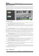


Table Of Contents
- 1. Updates
- 2. Product Introduction
- 3. Software Interface
- 3.1 Welcome Page
- 3.2 Home Page
- 3.3 Menu
- 3.4 Control Toolbar
- 3.5 Tool Box
- 3.6 Result Display
- 3.7 Flow Management
- 3.8 Camera Management
- 3.9 Controller Management
- 3.10 Global Variables
- 3.11 Communication Management
- 3.12 Global Trigger
- 3.13 Global Script
- 3.14 Operation Interface
- 3.15 Data Queue
- 3.16 Flow Time
- 3.17 Dobot Panel
- 4. Vision Tools
- 4.1 Acquisition
- 4.2 Location
- 4.2.1 Feature Match
- 4.2.2 Greyscale Match
- 4.2.3 Mark Location
- 4.2.4 Circle Search
- 4.2.5 Line Search
- 4.2.6 Blob Analysis
- 4.2.7 Caliper
- 4.2.8 Edge Search
- 4.2.9 Position Correction
- 4.2.10 Rect Search
- 4.2.11 Peak Search
- 4.2.12 Edge Intersection
- 4.2.13 Parallel Lines Search
- 4.2.14 Quadrilateral Search
- 4.2.15 Line Group Search
- 4.2.16 Multi-line Search
- 4.2.17 Blob Label Analysis
- 4.2.18 Path Extraction
- 4.2.19 Find Angle Bisector
- 4.2.20 Find Median Line
- 4.2.21 Calculate Parallel Lines
- 4.2.22 Find Vertical Line
- 4.3 Measurement
- 4.4 Image Generation
- 4.5 Recognition
- 4.6 Deep Learning
- 4.7 Calibration
- 4.8 Calculation
- 4.9 Image Processing
- 4.9.1 Image Combination
- 4.9.2 Image Morphology
- 4.9.3 Image Binarization
- 4.9.4 Image Filter
- 4.9.5 Image Enhancement
- 4.9.6 Image Computing
- 4.9.7 Distortion Correction
- 4.9.8 Image Clarity
- 4.9.9 Image Fixture
- 4.9.10 Shade Correction
- 4.9.11 Affine Transformation
- 4.9.12 Ring Expansion
- 4.9.13 Copy and Fill
- 4.9.14 Frame Mean
- 4.9.15 Image Normalization
- 4.9.16 Image Correction
- 4.9.17 Geometric Transformation
- 4.9.18 Image Stitch
- 4.9.19 Multiple Images Fusion
- 4.10 Color Processing
- 4.11 Defect Detection
- 4.11.1 OCV
- 4.11.2 Arc Edge Defect Detection
- 4.11.3 Linear Edge Defect Detection
- 4.11.4 Arc-Pair Defect Detection
- 4.11.5 Line-Pair Defect Detection
- 4.11.6 Edge Group Defect Detection
- 4.11.7 Edge Pair Group Defect Detection
- 4.11.8 Edge Model Defect Detection
- 4.11.9 Edge Pair Model Defect Detection
- 4.11.10 Defect Contrast
- 4.12 Logic Tools
- 4.13 Communication
- 4.14 Dobot Magician Tools
- 5. Cases
- 6. Dobot Magician Demo

DobotVisionStudio User Guide
Issue V4.1.2 (2022-06-08) User Guide Copyright © Yuejiang Technology Co., Ltd.
134
Distance to Remove
It means the maximum pixel distance from the outlier to the fit circle. The smaller the
value is, the more points are excluded.
Initial Type
It includes global optimum and local optimum
Weighting Function
It has three types, including least squares, huber function and tukey function. These three
fitting modes are different in way of calculating the weight only. As the number of outliers
and the distance from the group increases, it is recommended to use least squares, huber,
and tukey successively.
Max Iteration Times
max. execution times for fitting algorithm
Line fitting needs two fitting points, and its principle is similar to circle fitting. For specific
parameters, refer to circle fitting mentioned above. Take a solution demonstration as an example
here. The circle is used as the model for feature matching, and then the matching points are used to
fit the line.
Geometry Generation
The tool of geometry generation is used to freely create multiple auxiliary graphics, including
rectangles, points, line segments and circles. When some graphics are difficult to locate, you can
move the mouse or modify the X and Y coordinates to change the position of the generated
graphics, as shown below. The white circle contour that is difficult to locate can be created by
yourself.