
Manual

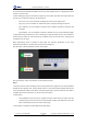


Table Of Contents
- 1. Updates
- 2. Product Introduction
- 3. Software Interface
- 3.1 Welcome Page
- 3.2 Home Page
- 3.3 Menu
- 3.4 Control Toolbar
- 3.5 Tool Box
- 3.6 Result Display
- 3.7 Flow Management
- 3.8 Camera Management
- 3.9 Controller Management
- 3.10 Global Variables
- 3.11 Communication Management
- 3.12 Global Trigger
- 3.13 Global Script
- 3.14 Operation Interface
- 3.15 Data Queue
- 3.16 Flow Time
- 3.17 Dobot Panel
- 4. Vision Tools
- 4.1 Acquisition
- 4.2 Location
- 4.2.1 Feature Match
- 4.2.2 Greyscale Match
- 4.2.3 Mark Location
- 4.2.4 Circle Search
- 4.2.5 Line Search
- 4.2.6 Blob Analysis
- 4.2.7 Caliper
- 4.2.8 Edge Search
- 4.2.9 Position Correction
- 4.2.10 Rect Search
- 4.2.11 Peak Search
- 4.2.12 Edge Intersection
- 4.2.13 Parallel Lines Search
- 4.2.14 Quadrilateral Search
- 4.2.15 Line Group Search
- 4.2.16 Multi-line Search
- 4.2.17 Blob Label Analysis
- 4.2.18 Path Extraction
- 4.2.19 Find Angle Bisector
- 4.2.20 Find Median Line
- 4.2.21 Calculate Parallel Lines
- 4.2.22 Find Vertical Line
- 4.3 Measurement
- 4.4 Image Generation
- 4.5 Recognition
- 4.6 Deep Learning
- 4.7 Calibration
- 4.8 Calculation
- 4.9 Image Processing
- 4.9.1 Image Combination
- 4.9.2 Image Morphology
- 4.9.3 Image Binarization
- 4.9.4 Image Filter
- 4.9.5 Image Enhancement
- 4.9.6 Image Computing
- 4.9.7 Distortion Correction
- 4.9.8 Image Clarity
- 4.9.9 Image Fixture
- 4.9.10 Shade Correction
- 4.9.11 Affine Transformation
- 4.9.12 Ring Expansion
- 4.9.13 Copy and Fill
- 4.9.14 Frame Mean
- 4.9.15 Image Normalization
- 4.9.16 Image Correction
- 4.9.17 Geometric Transformation
- 4.9.18 Image Stitch
- 4.9.19 Multiple Images Fusion
- 4.10 Color Processing
- 4.11 Defect Detection
- 4.11.1 OCV
- 4.11.2 Arc Edge Defect Detection
- 4.11.3 Linear Edge Defect Detection
- 4.11.4 Arc-Pair Defect Detection
- 4.11.5 Line-Pair Defect Detection
- 4.11.6 Edge Group Defect Detection
- 4.11.7 Edge Pair Group Defect Detection
- 4.11.8 Edge Model Defect Detection
- 4.11.9 Edge Pair Model Defect Detection
- 4.11.10 Defect Contrast
- 4.12 Logic Tools
- 4.13 Communication
- 4.14 Dobot Magician Tools
- 5. Cases
- 6. Dobot Magician Demo

DobotVisionStudio User Guide
Issue V4.1.2 (2022-06-08) User Guide Copyright © Yuejiang Technology Co., Ltd.
129
• By Line: inputting source is the result of finding line.
• By Point: you can customize or link the start point, end point and angle of the line.
• By Coordinate: you can customize or link the X/Y coordinate of the line's start point, and
end point.
• Running Operation: see L2C Measure for details.
L2L Measure Results
• By Angle: the angle difference between two lines.
• Distance: the average distance from four end points of the line to another line.
• Absolute Distance: the absolute value of distance.
• Intersection Point X/Y: the intersection point X/Y coordinate of extension lines of two
lines.
P2C, P2L, P2P Measure
For P2C, P2L and P2P measurement, please refer to L2C Measure. You can set the output of
corresponding tools according to your demands.
Intensity Measure
The tool of intensity measurement is used to measure grayscale average value and standard deviation
of all pixels within the ROI of the measured image. Select the image source in the operating area
first, drag the intensity measurement algorithm module into the operating area, and connect the
module in turn using the operating line. You can use ROI tool to select area and narrow the search
range. Click Run to see the result, as shown below.
Output Results
• Min./Max. Value: Min./Max. grayscale value
• Average Value: grayscale average value