
Manual
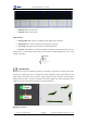


Table Of Contents
- 1. Updates
- 2. Product Introduction
- 3. Software Interface
- 3.1 Welcome Page
- 3.2 Home Page
- 3.3 Menu
- 3.4 Control Toolbar
- 3.5 Tool Box
- 3.6 Result Display
- 3.7 Flow Management
- 3.8 Camera Management
- 3.9 Controller Management
- 3.10 Global Variables
- 3.11 Communication Management
- 3.12 Global Trigger
- 3.13 Global Script
- 3.14 Operation Interface
- 3.15 Data Queue
- 3.16 Flow Time
- 3.17 Dobot Panel
- 4. Vision Tools
- 4.1 Acquisition
- 4.2 Location
- 4.2.1 Feature Match
- 4.2.2 Greyscale Match
- 4.2.3 Mark Location
- 4.2.4 Circle Search
- 4.2.5 Line Search
- 4.2.6 Blob Analysis
- 4.2.7 Caliper
- 4.2.8 Edge Search
- 4.2.9 Position Correction
- 4.2.10 Rect Search
- 4.2.11 Peak Search
- 4.2.12 Edge Intersection
- 4.2.13 Parallel Lines Search
- 4.2.14 Quadrilateral Search
- 4.2.15 Line Group Search
- 4.2.16 Multi-line Search
- 4.2.17 Blob Label Analysis
- 4.2.18 Path Extraction
- 4.2.19 Find Angle Bisector
- 4.2.20 Find Median Line
- 4.2.21 Calculate Parallel Lines
- 4.2.22 Find Vertical Line
- 4.3 Measurement
- 4.4 Image Generation
- 4.5 Recognition
- 4.6 Deep Learning
- 4.7 Calibration
- 4.8 Calculation
- 4.9 Image Processing
- 4.9.1 Image Combination
- 4.9.2 Image Morphology
- 4.9.3 Image Binarization
- 4.9.4 Image Filter
- 4.9.5 Image Enhancement
- 4.9.6 Image Computing
- 4.9.7 Distortion Correction
- 4.9.8 Image Clarity
- 4.9.9 Image Fixture
- 4.9.10 Shade Correction
- 4.9.11 Affine Transformation
- 4.9.12 Ring Expansion
- 4.9.13 Copy and Fill
- 4.9.14 Frame Mean
- 4.9.15 Image Normalization
- 4.9.16 Image Correction
- 4.9.17 Geometric Transformation
- 4.9.18 Image Stitch
- 4.9.19 Multiple Images Fusion
- 4.10 Color Processing
- 4.11 Defect Detection
- 4.11.1 OCV
- 4.11.2 Arc Edge Defect Detection
- 4.11.3 Linear Edge Defect Detection
- 4.11.4 Arc-Pair Defect Detection
- 4.11.5 Line-Pair Defect Detection
- 4.11.6 Edge Group Defect Detection
- 4.11.7 Edge Pair Group Defect Detection
- 4.11.8 Edge Model Defect Detection
- 4.11.9 Edge Pair Model Defect Detection
- 4.11.10 Defect Contrast
- 4.12 Logic Tools
- 4.13 Communication
- 4.14 Dobot Magician Tools
- 5. Cases
- 6. Dobot Magician Demo

DobotVisionStudio User Guide
Issue V4.1.2 (2022-06-08) User Guide Copyright © Yuejiang Technology Co., Ltd.
103
There are two ways to correct position: position correction by point and position coordinate by
coordinate. For by point, the position of the point has been determined. For by coordinate, X and Y
are used to determine the position of the point. Please note that whether for a point or a coordinate,
its position information is transmitted from the previous module, and its role is to determine the
pixel and angle deviation.
NOTE
When using fast feature matching and position correction, you do not need to be
subscribe the scale parameters. In this case, the position correction of images with the
same resolution but different sizes cannot be realized. When you use high-precision
feature matching and position correction, the position correction module automatically
subscribes the scale to realize the position correction of images with the same
resolution but different sizes.
The following are images before and after position correction.