
User Guide
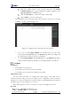
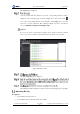
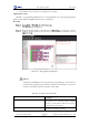
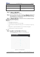


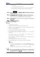

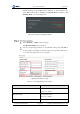
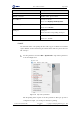
Table Of Contents
- 1. Security Precautions
- 2. Introduction
- 3. Hardware Installation
- 4. Electrical Specifications
- 5. Installation and Commissioning
- 5.1 Installing Software
- 5.2 Connecting Power Supply
- 5.3 Connecting Emergency Stop Switch
- 5.4 Connecting External Cables
- 5.5 System Commissioning
- 6. Operation
- 7. Maintenance

Dobot M1 User Guide 6 Operation
Issue V1.0.4 (2018-08-30) User Guide Copyright © Yuejiang Technology Co., Ltd
69
The picture (such as BMP, JPEG, JPG, PNG, and so on) is supported.
Figure 6.17 Import picture
NOTICE
The imported picture should be placed in the annular region, as shown in Figure
6.17. If not, it is unable to engrave normally and the border of the imported picture
will be highlighted in red.
The annular region depends on arm orientation. Please adjust the imported picture
according to the real annular region. Figure 6.17 shows the annular region when arm
orientation is left.
The Laser Setting page is displayed.
Please set the laser engraving parameters based on site requirements.
Table 6.7 Laser engraving parameters
Parameter
Description
CP Vel/ CP Acc
Set the rate of CP velocity and acceleration
PTP Vel/ PTP Jerk
Set the rate of PTP velocity and jerk