
User Guide
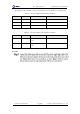
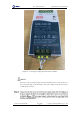
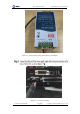
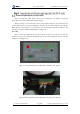

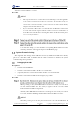
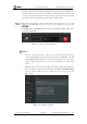
Table Of Contents
- 1. Security Precautions
- 2. Introduction
- 3. Hardware Installation
- 4. Electrical Specifications
- 5. Installation and Commissioning
- 5.1 Installing Software
- 5.2 Connecting Power Supply
- 5.3 Connecting Emergency Stop Switch
- 5.4 Connecting External Cables
- 5.5 System Commissioning
- 6. Operation
- 7. Maintenance

Dobot M1 User Guide 5 Installation and Commissioning
Issue V1.0.4 (2018-08-30) User Guide Copyright © Yuejiang Technology Co., Ltd
35
The input and output interfaces of the power adapter are shown in Table 5.1 and Table 5.2.ss
Table 5.1 The power adapter input interface description
No.
Name
Function
Voltage/Current
1
AC_L
L of the AC power
100V-240V AC/2.6A
2
AC_N
N of the AC power
100V-240V AC/2.6A
3
GND
GND
GND
Table 5.2 The power adapter output interface description
No.
Name
Function
Voltage/Current
1
A+
Positive electrode of the DC
power
48V DC/5A
2
A-
Negative electrode of the DC
power
GND/5A
Procedure