
User Guide
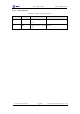

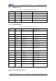

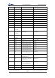
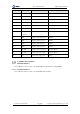
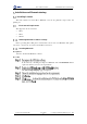
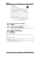
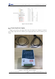
Table Of Contents
- 1. Security Precautions
- 2. Introduction
- 3. Hardware Installation
- 4. Electrical Specifications
- 5. Installation and Commissioning
- 5.1 Installing Software
- 5.2 Connecting Power Supply
- 5.3 Connecting Emergency Stop Switch
- 5.4 Connecting External Cables
- 5.5 System Commissioning
- 6. Operation
- 7. Maintenance

Dobot M1 User Guide 4 Electrical Specifications
Issue V1.0.4 (2018-08-30) User Guide Copyright © Yuejiang Technology Co., Ltd
27
4.3.2.2 Base I/O Interface
Table 4.6 Description of the base I/O interface
PIN
Name
Function
Voltage/Current
1
PGND
Negative electrode of the logic
power
GND/2A
2
VCC
Positive electrode of the logic
power
24V DC/2A
3
RS232_RX
RS232 acception
RS232 level
4
RS232_TX
RS232 transmission
RS232 level
5
STOP2+
Positive electrode of the safety
input 2, used for connecting to
emergency stop switch
0V,24V/<100mA
6
STOP1+
Positive electrode of the safety
input 1, used for connecting to
emergency stop switch
0V,24V/<100mA
7
STOP2-
Negative electrode of safety
input 2, used for connecting to
emergency stop switch
0V,24V/<100mA
8
STOP1-
Negative electrode of safety
input 1, used for connecting to
emergency stop switch
0V,24V/<100mA
9
DOUT17
Digital output
0V,24V/2mA
10
DOUT18
Digital output
0V,24/2mA
11
DIN_20
Digital input
0V,24V/<100mA
12
DIN_18
Digital input
0V,24V/<100mA
13
DIN_19
Digital input
0V,24V/<100mA
14
DIN_17
Digital input
0V,24V/<100mA