
User Guide
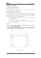
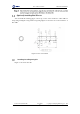
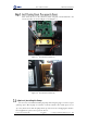
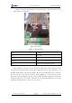
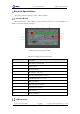
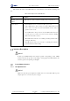
Table Of Contents
- 1. Security Precautions
- 2. Introduction
- 3. Hardware Installation
- 4. Electrical Specifications
- 5. Installation and Commissioning
- 5.1 Installing Software
- 5.2 Connecting Power Supply
- 5.3 Connecting Emergency Stop Switch
- 5.4 Connecting External Cables
- 5.5 System Commissioning
- 6. Operation
- 7. Maintenance

Dobot M1 User Guide 3 Hardware Installation
Issue V1.0.4 (2018-08-30) User Guide Copyright © Yuejiang Technology Co., Ltd
20
Figure 3.9 shows the air pump. Table 3.1 lists the description of the cables that are shown
in the yellow box of this figure.
Figure 3.9 Air pump
Table 3.1 Cable Description
Color
Description
Red
VCC_24V
Black
PGND
Yellow
OUT1: Control the intake and outtake of the air pump
Blue
OUT2: Control the status of the air pump
If the air pump is connected to the base I/O interface. The yellow cable and the blue one are
connected to the output pins (The corresponding outputs listed in 4.3.2.2 Base I/O Interface are
DOUT17 and DOUT18) of the base I/O interface. The red one and the black one are connected to
the VCC_24V pin on the base I/O interface and the PGND pin on the CAN bus interface
respectively, as shown in Figure 3.10, and you need to tighten them with a straight screwdriver. The
description in this topic is for reference only. Please choose the appropriate interface to connect the
air pump. For details, please see 4.3 Interface Description.