
User Guide
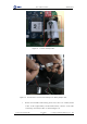
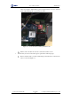

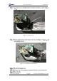
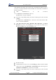
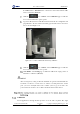
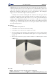
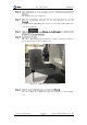
Table Of Contents
- 1. Security Precautions
- 2. Introduction
- 3. Hardware Installation
- 4. Electrical Specifications
- 5. Installation and Commissioning
- 5.1 Installing Software
- 5.2 Connecting Power Supply
- 5.3 Connecting Emergency Stop Switch
- 5.4 Connecting External Cables
- 5.5 System Commissioning
- 6. Operation
- 7. Maintenance

Dobot M1 User Guide 7 Maintenance
Issue V1.0.4 (2018-08-30) User Guide Copyright © Yuejiang Technology Co., Ltd
102
If Connect turns to Disconnect, the connection is successful, and Dobot M1
can be controlled by M1Studio.
Click the icon of Motor on the Calibration page to make the
motor of Dobot M1 in the open-loop state.
Jog Dobot M1 by hand to make Rear Arm and Forearm in a straight line and
perpendicular to the base forward, and then jog Dobot M1 to the bottom of Z-
axis, as shown in Figure 7.16.
Figure 7.16 Location of Dobot M1 after Factory calibration
Click the icon of Motor on the Calibration page to make the
motor of Dobot M1 in the close-loop state.
Click InitPos on the Debug page to make Dobot M1 in the origin position of
which the coordinate is (400,0,0,0).
NOTICE
After restoring factory setting, an alarm about limitation is generated and meanwhile the
red indicator on the base of robotic arm is on, which is a normal phenomenon. At that
point, you need to click J3+ under Joint coordinate system to jog robotic arm to the
position where the J3 value is above 10mm, and then the alarm will be cleared.
Calibration
In real applications, the high absolute precision of robotic arm is required. The origin