User Guide M1 Pro Hardware User Guide Issue: V1.1 Date: 2021-07-08 Shenzhen Yuejiang Technology Co.
Dobot M1 PRO Hardware User Guide Copyright © Shenzhen Yuejiang Technology Co., Ltd 2021. All rights reserved. No part of this document may be reproduced or transmitted in any form or by any means without the prior written consent of Yuejiang Technology Co., Ltd. Disclaimer To the maximum extent permitted by applicable law, the products described (including its hardware, software, and firmware, etc.) in this document are provided AS IS, which may have flaws, errors or faults.
Dobot M1 Pro Hardware User Guide Preface Purpose This Document describes the functions, technical specifications, installation guide of Dobot M1 Pro robot, making it easy for users to fully understand and use it. Intended Audience This document is intended for: Customer Sales Engineer Installation and Commissioning Engineer Technical Support Engineer Change History Date Change Description 2021/04/23 The first releases. 2021/07/08 Add the general security.
Dobot M1 Pro Hardware User Guide Contents Security Precautions ................................................................................................ 1 Security Warning Sign ...................................................................................................... 1 General Security................................................................................................................ 1 Personal Security .........................................................................
Dobot M1 PRO Hardware User Guide Security Precautions This topic describes the security precautions that should be noticed when using this product. Please read this document carefully before using the robot for the first time. This product needs to be carried out in an environment meeting design specification. You cannot remold the product without authorization, otherwise, it could lead to product failure, and even personal injury, electric shock, fire, etc.
Dobot M1 PRO Hardware User Guide circuit, otherwise, it is vulnerable to injury the device or the person. You should comply with the local laws and regulations when operating the robot. The security precautions in this document are only supplemental to the local laws and regulations. Please use the robot in the specified environment scope. If not, exceeding the specifications or load conditions will shorten the service life of the robot, even damage it.
Dobot M1 PRO Hardware User Guide When the robot is transported, the packaging needs to be fixed to ensure that the robot is stable. After removing the outer packaging, please make sure that the robot maintains the original packing posture and the brakes on each axis are normal. During the commissioning process, it is necessary to confirm that no relevant personnel and equipment (include computer used for debugging) stay in the dangerous area of the machine.
Dobot M1 PRO Hardware User Guide RF source without shielding, otherwise, it could lead to robot abnormally. When the operator commissioning or operates the equipment, it shall be done in the safe space of the equipment. WARNING In order to protect the equipment and personal safety, when turning off the power, please press the switch, then unplug the AC power cable. The power is disconnected by plug and socket.
Dobot M1 PRO Hardware User Guide Do not touch the terminal blocks or remove the interval circuit components in 10 minutes after the power is shut off, to avoid an electric shock since there is residual capacitance inside the robot. Even if the power switch of the robot is already in the OFF status, touching the terminal blocks or removing the interval circuit components is not allowed, to avoid an electric shock since there is residual capacitance inside the robot.
Dobot M1 PRO Hardware User Guide Overview Dobot Master 2nd generation robotic arm (Dobot M1 Pro for short) focuses on the light industrial market with great potential, and supports teaching, playback, script control, blockly, vision identity and other functions, which is flexibly used in intelligent sorting, circuit board soldering and other automatic production lines, so that it can become the sword to solve practical problems for light industrial users, and can also become the platform to carry the imagi
Dobot M1 PRO Hardware User Guide Technical Specifications Table 2.1 M1 Pro technical parameters Product DOBOT M1 Pro Model DT-M1-P4R15-01I Weight 15.7kg Max load 1.5kg Reach 400mm Power supply 100~240 VAC,50/60Hz Rated voltage DC48V Installation Table installation, indoor Rated power 192W Repeatability ±0.
Dobot M1 PRO Hardware User Guide USB 2.0 Temperature range 2 Storage temperature:-25℃~55℃ Working temperature:0℃~40℃ Operating altitude range ≤ 1000 m Safety Standard EN ISO 10218-1:2011 Steel wire and wire products. General. Test methods EN 60204-1:2018 Safety of machinery. Electrical equipment of machines. General requirements EN ISO 12100:2010 Safety of machinery. General principles for design. Risk assessment and risk reduction EMC Standard EN 61000-6-2:2019 Electromagnetic compatibility (EMC).
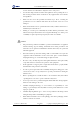
Dobot M1 PRO Hardware User Guide You can install the matching gripper, suction cup on the end of the M1 Pro for transporting and intelligent sorting. Figure 2.3 shows the dimension of end-effector. Figure 2.3 End-effector dimension Robot Workspace Figure 2.4 shows the workspace of M1 Pro robot. Figure 2.4 M1 Pro robot workspace NOTICE Issue V1.1 (2021-07-08) User Guide 9 Copyright © Yuejiang Technology Co.
Dobot M1 PRO Hardware User Guide When operating the robot, be sure to operate inside the workspace. End Flange Size Figure 2.5 End flange size Stop Time and Angle The Max. stop time and angle of axis J1, J2, J3 and J4 at the max speed, load and arm stretch are shown below. Table 2.2 Stop time and angle Axis Max. stop angle(°) Max. stop time(ms) J1 9.6 103 J2 9.4 102 J4 36.5 100 Axis Max. stop distance(mm) Max.
Dobot M1 PRO Hardware User Guide When the robot leaves the factory, moving robot to the factory point can reduce the robot space, easy to pack and transport. Figure 2.6 shows the factory point. The robot has 4 joints, respectively J1, J2, J3 and J4, please see 2.8.2.1 Joint Coordinate System for explanation of joints. The joint angles corresponding to the factory point are: J1= 0°, J2= 0°, J3= 0mm, and J4= 0°. Adjust joint Angles by jog or programming.
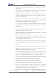
Dobot M1 PRO Hardware User Guide Figure 2.7 Righty hand orientation Figure 2.8 Lefty hand orientation Coordinate System 2.8.2.1 Joint Coordinate System The Joint coordinate system is determined by the motion joints. Figure 2.9 shows the Joint coordinate system of a M1 Pro robot. All the joints are rotating joints. M1 Pro contains four joints. J1, J2, and J4 are the rotating joints, which are located and oriented in the horizontal plane. And their axes are parallel to each other.
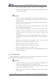
Dobot M1 PRO Hardware User Guide J3 is the moving joint, which is used for the movement of the end effector in the perpendicular plane. The positive direction of J3 is vertical upward. Figure 2.9 Joint coordinate of a M1 Pro robot 2.8.2.2 Base Coordinate System The Base coordinate system is determined by the base. Figure 2.10 shows the Base coordinate system of M1 Pro robot. The origin is the axes center of the motor of Rear Arm where Rear Arm is dropped to the bottom of the Z-axis screw.
Dobot M1 PRO Hardware User Guide Figure 2.10 Base coordinate system of M1 Pro robot 2.8.2.3 Tool Coordinate System Tool coordinate system is the coordinate system that defines the distance and rotation angle of the offset, of which the origin and orientations vary with the position and attitude of the workpiece located at the robot flange. The 10 types of tool coordinate systems can be defined.
Dobot M1 PRO Hardware User Guide Figure 2.11 The default Tool coordinate system of M1 Pro robot 2.8.2.4 User Coordinate System The User coordinate system is a movable coordinate system which is used for representing equipment like fixtures, workbenches. The origin and the orientations of axes can be defined based on site requirements, to measure point data within the workspace and arrange tasks conveniently. Figure 2.12 Issue V1.
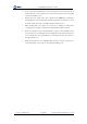
Dobot M1 PRO Hardware User Guide Electrical Specifications Interface of Base External Interface Board Description Figure 3.1 shows the interface board of the Base. Table 3.1 lists the description. Figure 3.1 Interface board of the base Table 3.1 screen printing Description Ethernet1 Ethernet interface Interface description The default IP address is 192.168.1.6, which cannot be modified.
Dobot M1 PRO Hardware User Guide screen printing Description I/O I/O interface The Encoder interface of the M1 Pro is shown in Figure 3.2,Table 3.2 lists the description of Encoder interface. Figure 3.2 Table 3.2 No. Description Encoder interface Encoder Interface description 1 2 3 4 5 6 7 8 9 ABZ_A+ ABZ_A- ABZ_B+ ABZ_B- ABZ_Z+ ABZ_Z- 5V 0V unused A robot controller contains I/O interfaces, for connecting to external equipment, such as PLC, etc.
Dobot M1 PRO Hardware User Guide Figure 3.4 Table 3.3 Simple digital input circuit Technical specifications Item Specification Input channel 16 channels Connection method Europe type terminal Input type PNP Input voltage (DC) 24V±10% Isolation method Optical coupling isolation Digital Output Figure 3.5 shows the simple digital output circuit and Table 3.4 lists the technical specifications. Figure 3.5 Issue V1.
Dobot M1 PRO Hardware User Guide Table 3.4 Technical specifications Item Specification Output channel 16 channels Connection method Europe type terminal Output type PNP Power supply (DC) 24V±10% Load current of single channel 500mA Output current 2A Isolation method Magnetic isolation End-effector I/O Interface Description The end-effector I/O interfaces of the M1 Pro include a RS485 interface, 4 digital inputs and 4 digital outputs, as shown in Figure 3.6, Table 3.
Dobot M1 PRO Hardware User Guide Installation Installation Environment To maintain the controller and robot performance and to ensure the safety, please place them in an environment with the following conditions. Install indoors with good ventilation. Keep away from excessive and shock. Keep away from direct sunlight. Keep away from dust, oily smoke, salinity, metal powder, corrosive gases, and other contaminants. Keep away from flammable.
Dobot M1 PRO Hardware User Guide Maintenance and Repair Maintenance and repairing must be performed in compliance with all safety instructions in this manual. The purpose of maintenance and repairing is to ensure that the system is kept operational, or to return the system to an operational state in the event of a fault. Repairing includes troubleshooting in addition to the actual repair itself. Repairing must be performed by an authorized system integrator or Dobot staff.
Dobot M1 PRO Hardware User Guide with water or 10% alcohol Observe the moving part of the cable, check √ Cable, cable whether the cable is damaged, whether there is protective cover local bending or distortion; Check whether the cable protective cover is damaged, etc.