
User manual

VediView
can analyse vessels positioned in either the vertical or horizontal planes.
The congure analysis dialog box can be used to select the appropriate orientation of
vessel (default vertical). This feature is useful in some microscope set-ups where the
vessel appears horizontal in the captured image.
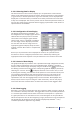
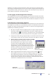
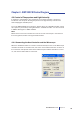
3.3.4.5 Logging and Reviewing Results of Analysis
The conguration and control of data logging is performed from the data control bar.
If image analysis is active, the derived parameters are passed to the data control bar
for display and or logging to le. This is also the case when the sequencer is active or
otherwise.
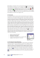
3.4 Calibration of the Image Analysis
The image processing functions in VediView
can be performed in units derived from
the image data (i.e. pixels) or can be dened by means of a calibration. This involves
imaging of an object of known dimensions (such as a reticule). The Image Analysis is
calibrated by the following procedure:
1. Set up the complete culture myograph system to image an object of known
dimensions. Make sure the frame grabber control bar is visible (select the
frame grabber icon in the tool bar) and appears in the main window. Make
sure the frame grabber is in live mode from the frame grabber control bar.
2. Using the live video setting, image the object in the main window and use the
zoom facility to obtain the most accurate view of the test object (or reticule).
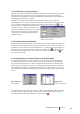
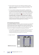
3. Click and drag in the main window to select a rectangleClick and drag in the main window to select a rectangle
that overlay the object (or reticule) in such a way
that the dimensions of the object can be matched
to those of the rectangle (Fig.3.25). Note that this
rectangle is red. If the rectangle is incorrectly drawn,
simply redraw it until you are satised with its size and
position. A calibration only needs to be performed in
one dimension (usually horizontal or vertical), if the
dimensions of the image are isotropic.
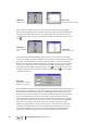
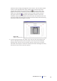
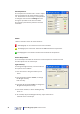
4. Select image calibration from either the pop up menu (click on ) on the
frame grabber control bar or select the ”calibrate image” icon on the tool
bar. A dialog box will appear to enter the rectangle dimensions appropriate
for the known dimensions of the test object (or reticule). Note that if the
isotropic option is selected, only one dimension is required (in this case the
x-dimension is 328.543 microns) to set the other.
Figure 3.21
No image analysis possible
Figure 3.23
One edge analysis
Figure 3.25
Calibration rectangle
Figure 3.26
Calibration of image analysis
35
User Manual vers. 1.4 Chapter 3