
User guide

44
S1 User Handbook
5
CONNECTORS AND CABLING
CONNECTORS AND CABLING
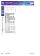
5 Connectors and Cabling
Many of the problems associated with installing and maintaining a mixing console are due
to the use of poor cables or faulty connections. It is recommended that, wherever possible,
pre-wired cables are purchased from recommended manufacturers. If you need bespoke
cables making, please ensure that a qualied engineer carries out the work.
The main types of connectors used with the S1 mixers are the following:
XLR 3 Pin Connectors
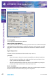
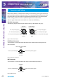
The following diagram shows the pin details for the 3 pin XLR sockets and plugs:
Pin 2. Hot (In Phase) Signal
Pin 1. Ground (Screen) Signal
Pin 3. Cold (Out Of Phase) Signal
3 Pin Socket
(Female)
Line, Mic &
AES/EBU Inputs
C/F, L/R Stereo &
AES/EBU Outputs
3 Pin Socket
(Male)
Pin 2. Hot (In Phase) Signal
Pin 1. Ground (Screen) Signal
Pin 3. Cold (Out Of Phase) Signal
Fig 5-1: XLR 3 Pin Connectors
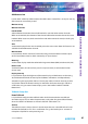
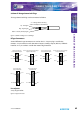
RCA Phono Connector
This connector is used on the Stereo RCA Channels and the S/PDIF on the digital input/
output channels.
Inner. Hot (In Phase) Signal Outer. Ground (Screen) Signal
Stereo Left & Right & S/PDIF
Inputs
RCA Phono
(Female)
Fig 5-2: RCA Phono Connector
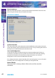
BNC Connector
This connector is used for the Word clock inputs on the PGM output channel.
Inner. Hot (In Phase) Signal Outer. Ground (Screen) Signal
Word Clock
Inputs
BNC (Female)
Fig 5-3: BNC Connector