
Installation Guide


2 1102 INSTALLATION GUIDE | DIGITAL MONITORING PRODUCTS
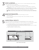
MOUNT THE TRANSMITTER
When mounting the 1102, refer to Figure 2for battery and mounting hole locations.
1. Remove the battery.
2. Place the supplied #4screw into the mounting hole and secure the transmitter to the surface.
3. Reinsert the battery.
4
5
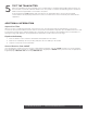
WIRE EXTERNAL CONTACTS
Refer to Zone Information in the appropriate panel programming guide for more information. DMP
recommends using 18or 22AWG unshielded wire for contact connections. Do not use twisted pair or shielded
wire.
1. Use a flathead screwdriver to loosen the two screws on the external contact terminal block.
2. Insert external contact wiring into the 1102terminal block and tighten the screws.
3. Connect the other ends of the wires to the external contact as either normally open (N/O) or normally
closed (N/C) without an end‑of‑line resistor.
4. Snap the transmitter cover back onto the base.
3
The 1102 provides a Survey LED capability to allow one person to confirm communication with the wireless
receiver or panel while the cover is removed.
1. With the cover removed, hold the transmitter in the exact desired location.
2. Press the tamper switch to send data to the panel and determine if communication is confirmed or
faulty.
Confirmed: If communication is confirmed, for each press or release of the tamper switch, the LED
blinks immediately on and immediately o. Repeat this test to confirm five separate consecutive LED
blinks. Any indication otherwise means proper communication has not been established.
Faulty: If communication is faulty, the LED remains on for about 8 seconds or flashes multiple times
in quick succession. Relocate the transmitter or receiver until the LED confirms clear communication.
SELECT A LOCATION
EXTERNAL CONTACTS
External Contact
Terminal Block
1102
External
Contact
Magnet
Figure 3: External Contact Wiring