
Installation guide


Digital Monitoring Products XR5 Installation Guide
10
INSTALLATION
XR5 Installation Guide Digital Monitoring Products
11
INSTALLATION
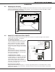
Bell Output
7.1 Terminal 5 (XR5FC Only)
Terminal 5 supplies 12 VDC Bell Output to power alarm bells or horns. The output is rated for a maximum
of 1.5 Amps. This output can be steady or pulsed depending upon the Bell Action specied in Output
Options programming. Terminal 10 is the ground reference for terminal 5.
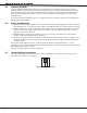
4-Wire Smoke Detector Power
8.1 Terminal 6 (XR5FC Only)
Terminal 6 provides up to 100mA at 12 VDC to power 4-wire smoke detectors or other auxiliary powered
devices. This output can be turned off by the user for 5 seconds using the Sensor Reset User Menu option.
Terminal 10 is the ground reference for terminal 6.
Keypad Bus
9.1 Description
Terminals 7, 8, 9, and 10 of the XR5FC and XR5SL panels provide the keypad bus to which you can connect
an unlimited number of 692F LED keypads, two alphanumeric Security Command keypads, and other
auxiliary devices.
9.2 Terminal 7 - RED
Terminal 7 provides 12 VDC keypad power for Security Command keypads. You can also connect 12 VDC
auxiliary devices to terminal 7. The ground reference for terminal 7 is terminal 10. The maximum output
is rated at 500mA on the XR5FC and XR5SL panels. All auxiliary devices totalled together must not exceed
the panel’s maximum current rating.
9.3 Terminal 8 - YELLOW
Data receive from devices.
9.4 Terminal 9 - GREEN
Data transmit to devices.
9.5 Terminal 10 - BLACK
Terminal 10 is the ground reference for keypads and any auxiliary devices powered by terminal 7.
Note: Do not use shielded wire when wiring keypads or other devices.
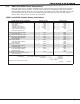
Class A (Style D) Fire Zone
10.1 Description
Terminals 11 to 14 are the panel’s Class A (Style D) re zone. This zone is suitable for connecting waterow
devices, heat detectors, and other non-powered re devices. For programming purposes, this is zone
number 1. The zone is rated for 1.66mA at 5.0 VDC.
The zone conguration on terminals 11 to 14 are described below.
Terminal Function Terminal Function
11 Zone 1 voltage sensing 12 Negative for terminal 11
13 Zone 1 voltage sensing 14 Negative for terminal 13
The voltage sensing terminal measures the voltage across the circuit and the zone’s negative terminal. Dry
contact sensing devices can be used only in parallel (normally-open) with zone 1. There are no End-of-Line
resistors on a Class A (Style D) zone.