
Installation guide


Digital Monitoring Products XR5 Installation Guide
4
INTRODUCTION
XR5 Installation Guide Digital Monitoring Products
5
INSTALLATION
Installation
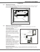
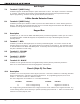
4.1 Mounting the Enclosure
The metal enclosure for the XR5FC and XR5SL panels must be mounted in a secure, dry place to protect the
panels from damage due to tampering or the elements. It is not necessary to remove the XR5FC or XR5SL
PC board when installing the enclosure.
3/4" x 1/2" Knockout
Two 1 3/4" Wire Opening
s
Extra Deep 3 3/4" Cabinet
3/4" x 1/2" Knockouts
Transformer Knockout
Figure 3: Mounting the Enclosure
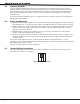
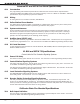
4.2 Model 377 Trouble Annunciator Module
The 377 Module is installed on the enclosure door and connects to the panel through a 4-wire harness
supplied with the module. See Figure 4.
377 Module Operation
The 377 Trouble Annunciator Module provides
visual and audible annunciation of System
Okay, communication trouble, and panel
processor failure. The module contains a
Green LED for System Okay, a Yellow LED for
Trouble, an electronic sounder, and a Silence
switch.
System Okay
When both phone lines are normal and the
panel processor is operating, only the Green
LED on the 377 Module is on. This LED goes
off during a Sensor Reset.
Communication Trouble
If either phone line connected to the panel is
in a bad condition, or if the panel has made
TEN failed attempts to send a report to the
central station receiver, the 377 Module
emits a steady audible alert and turns on the
Yellow LED. The Silence switch can be used
to turn off the sounder only.
Panel Processor Failure
During a processor failure on the panel, or a remote programming session, the 377 Module emits a steady
audible alert and turns on the Yellow LED. The Silence switch will not turn off the sounder or Yellow LED
during these conditions.
Figure 4: 377 Module Wiring