
Installation guide


Digital Monitoring Products XR5 Installation Guide
4
INTRODUCTION
XR5 Installation Guide Digital Monitoring Products
5
INSTALLATION
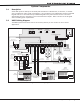
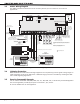
3.3 XR5SL Wiring Diagram
The XR5SL system below shows some of the accessory devices you can connect for use in various
applications.
Figure 2: XR5SL Wiring Diagram
3.4 Lightning Protection
Metal Oxide Varistors and Transient Voltage Suppressors on the panel help protect against voltage surges on
input and output circuits of the XR5 panels. Additional surge protection is available by installing the DMP
370 or 370RJ Lightning Suppressors.
3.5 Security Command® Keypads
You can connect the Models 690, 690F, 692F, 770, 771, 790, 790F, 791, or 793 Security Command keypads to
the 4-wire keypad bus provided by the panel on terminals 7, 8, 9, and 10.
Do not use shielded wire for the keypad bus.