
Installation guide
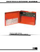


XR5 Installation Guide Digital Monitoring Products
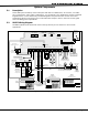
1
INTRODUCTION
Panel SpeciÞ cations
1.1 Power Supply
Primary Power Input: 16.5 VAC 40 VA (Model 320 wire-in) or 12/24 VDC from Fire Alarm Control Panel (FACP)
Standby Batteries: One or two 12 VDC 7.0 Ah
Auxiliary Output: 500mA at 12 VDC
Bell Output: 1.5 Amps at 12 VDC (XR5FC only)
Smoke Detector Output: 100mA at 12 VDC (XR5FC only)
All circuits inherent power limited except the red battery wire.
1.2 Communication
Built-in SDLC Digital Dialer communication to DMP Model SCS-1 and SCS-1R Receivers.
Built-in 4-2 communication to non-DMP receivers.
Built-in CID communication to non-DMP (Contact ID) receivers.
Can operate as a local system (XR5FC only).
1.3 Panel Zones
One Class A (Style D) zone (terminals 11 to 14).
Four 3.3K Ohm EOL Class B (Style A) powered Þ re zones with reset capability (terminals 15 to 22).
1.4 Remote Annunciators (Alphanumeric or LED Keypads)
You can connect alpha Security Command keypads and LED keypads to the XR5FC and XR5SL keypad bus.
The panels do not support zone expansion on the keypad bus.
1.5 Auxiliary Outputs
Two Form C (SPDT) outputs (Outputs 1 and 2). Each output requires one Model 305 plug-in relay. Each
relay is rated for 1 Amp at 30 VDC.
Four open collector annunciator outputs (Outputs 1 to 4). No relay is required. Each output is rated for
50mA at 30 VDC resistive.
1.6 Push-Button Reset
The XR5FC and XR5SL panels each provide a push button mounted on the printed circuit board that allows
authorized users to reset latch detectors and silence active alarm bell outputs. See section 16.1.
1.7 Enclosure SpeciÞ cations
The XR5 panels are shipped in an enclosure with End-of-Line resistors, battery leads, User’s Guide (LT-
0296), and Programming Sheet (LT-0297).
Size: 12.5” W x 9.5” H x 3.75” D
Weight: 4 lbs
Color: Red
Construction: 20-gauge cold-rolled steel