
Installation guide


XR5 Installation Guide Digital Monitoring Products
i
TABLE OF CONTENTS
Revisions to This Document
Panel SpeciÞ cations
1.1 Power Supply ......................................................................... 1
1.2 Communication ...................................................................... 1
1.3 Panel Zones ........................................................................... 1
1.4 Remote Annunciators (Alphanumeric or LED Keypads) .............. 1
1.5 Auxiliary Outputs.................................................................... 1
1.6 Push-Button Reset.................................................................. 1
1.7 Enclosure SpeciÞ cations .......................................................... 1
Introduction
2.1 Description ............................................................................ 2
2.2 Before you Begin.................................................................... 2
2.3 About this Guide .................................................................... 2
2.4 How to Use this Guide ............................................................ 2
System Components
3.1 Description ............................................................................ 3
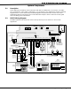
3.2 XR5FC Wiring Diagram............................................................ 3
3.3 XR5SL Wiring Diagram............................................................ 4
3.4 Lightning Protection ............................................................... 4
3.5 Security Command® Keypads ................................................. 4
Installation
4.1 Mounting the Enclosure .......................................................... 5
4.2 Model 377 Trouble Annunciator Module.................................... 5
4.3 Mounting Keypads.................................................................. 6
4.4 Wiring SpeciÞ cations............................................................... 6
4.5 Terminal Wiring Connections ................................................... 6
Primary Power Supply
5.1 Installing the Transformer ....................................................... 7
5.2 Terminals 1 and 2................................................................... 7
Secondary Power Supply
6.1 Battery Terminals 3 and 4 ....................................................... 8
6.2 Earth Ground ......................................................................... 8
6.3 Replacement Period................................................................ 8
6.4 Discharge/Recharge ............................................................... 8
6.5 Battery Supervision ................................................................ 8
6.6 XR5FC and XR5SL Power Requirements ................................... 9
XR5FC and XR5SL Standby Battery Calculations ................................... 9
Bell Output
7.1 Terminal 5 (XR5FC Only)........................................................10
4-Wire Smoke Detector Power
8.1 Terminal 6 (XR5FC Only)........................................................10
Keypad Bus
9.1 Description ...........................................................................10
9.2 Terminal 7 - RED ...................................................................10
9.3 Terminal 8 - YELLOW.............................................................10
9.4 Terminal 9 - GREEN ...............................................................10
9.5 Terminal 10 - BLACK..............................................................10