
Installation guide


Digital Monitoring Products XR5 Installation Guide
20
WIRING DIAGRAMS
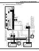
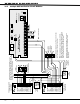
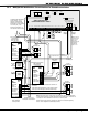
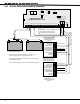
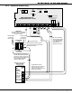
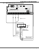
21.6 XR5SL Connection to FACP
AC
1
3
+B
5
BELL
6
SMK
11
Z1A+
7
RED
8
YEL
9
GRN
10
BLK
2
AC
4
-B
12
Z1A-
13
Z1B+
14
Z1B-
15
Z2+
16
Z2-
17
Z3+
18
Z3-
19
Z4+
20
Z4-
21
Z5+
22
Z5-
N/ON/C COMN/ON/C COM
J11
1
2
3
4
J12
OUTPUT 2
OUTPUT 1
MAIN
BACKUP
Telephone
Connections
J4 J5
Silence/Reset
Header
J13
J14
Bell
Monitor
Silence/Reset
Button
Silence/Reset
Push for 1 Second
Panel
Reset
J10 Trouble Annunciator Header
Relay Sockets for Optional
Form C Outputs on J11
XR5SL Commercial Fire
Command Processor™ Panel
W
W
Zone 1
SS SS
Positive 12/24 VDC Auxiliary Output
Zone 2
Zone 3
Zone 4
Negative 12/24 VDC Auxiliary Output
Main Fire Alarm
Control Panel (FACP)
{
{
{
{
Normally Open
Common
Normally Closed
Normally Open
Normally Open
Common
Common
Normally Closed
Normally Closed
Normally Open
Common
Normally Closed
3.3k Ohm
3.3k Ohm
3.3k Ohm
3.3k Ohm
Zone 5
DMP Model 320 Transformer
120 VAC
60Hz
350mA
AC Mode
Optional DC Mode
AC Mode Wiring
When the XR5SL is used in the
AC Mode, the DMP Model 320
Transformer must be connected
to the same branch circuit as the
FACP.
An AC power fail can then be
delayed 6 to 12 hours by the
XR5SL programming. See section
5.4 in the XR5 Programming
Guide
(LT-0312).
The FACP must not indicate AC
Fail to the XR5SL.
Form C alarm contacts
activate on General Alarm.
Form C trouble contacts
activate on General Trouble.
General Trouble must not be
used to indicate AS power fail
unless it can be delayed 6 to
12 hours.
Form C or A contacts activate
on Supervisory condition.
Form C contacts activate on
A
C power fail. Use on XR5SL
in DC Mode only. Must delay
A
C power fail 6 to 12 hours.
DC Mode Wiring
When the XR5SL is used in the DC
Mode, the operating range of the FACP
must be between 18 and 30 VDC.
The FACP must indicate AC power fail
on an independent relay output. This
output must delay the AC power fail 6
to 12 hours.