
Installation guide


XR5 Installation Guide Digital Monitoring Products
19
WIRING DIAGRAMS
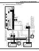
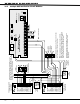
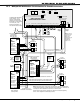
21.5 Supervised Remote Relay
AC
1
3
+B
5
BELL
6
SMK
11
Z1A+
7
RED
8
YEL
9
GRN
10
BLK
2
AC
4
-B
12
Z1A-
13
Z1B+
14
Z1B-
15
Z2+
16
Z2-
17
Z3+
18
Z3-
19
Z4+
20
Z4-
21
Z5+
22
Z5-
N/ON/C COMN/ON/C COM
J11
1
2
3
4
J12
OUTPUT 2
OUTPUT 1
MAIN
BACKUP
Telephone
Connections
J4 J5
Silence/Reset
Header
J13
Bell
Monitor
J14
Silence/Reset
Button
Silence/Reset
Push for 1 Second
Panel
Reset
J10 Trouble Annunciator Header
Relay Sockets for Optional
Form C Outputs on J11
XR5 Commercial Fire
Command Processor™ Panel
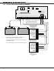
S
S
3.3K EOL
Zone 2
SS
W
W
Zone 1
SS SS
3.3K EOL
Zone 3
SS
3.3K EOL
Zone 3
SS
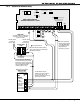
1 AUX PWR
2 GND
3 Alarm In
4 Bell PWR In
5 Bell Out +
6 Bell Out -
7 Bell Trouble
8 Bell Trouble
866
Module
Normal/Silence Switch
Notification Circuit Module
DMP Model 866
45mA @12 VDC
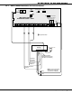
Remote DPDT
Relay
S
= Supervised Circuit
S
S
The 866 Module must be
installed in the panel enclosure
or in a 340FC, 349, or 350
Enclosure connected by no more
than 20 feet of conduit.
DPDT Relay
Use Model ASRB-1 from Advanced
Signaling. 30mA coil operating
current at 12 VDC.
3.3K EOL
Normally Open
contacts will
close on alarm.
Normally Closed
contacts will
Open on alarm.
10K EOL Resistor
DMP Model 308
DMP Part #DI-001 Rectifier (1N4001
diode) in series with input from Model
866 Module terminal 6.
Wiring between the 866 Module
and the DPDT Relay is supervised
against open, shorts, and grounds.
Any of these trouble conditions will
cause the 866 Module's Bell
Trouble contacts to open.
S
S
The zone connected to
the Bell Trouble contacts
on the 866 Notification
Circuit Module must be
programmed as a
Supervisory Type zone.