
Installation guide


Digital Monitoring Products XR5 Installation Guide
18
WIRING DIAGRAMS
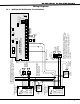
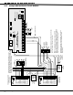
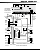
21.4 Remote Station Reversing Relay Connection
AC
1
3
+B
5
BELL
6
SMK
11
Z1A+
7
RED
8
YEL
9
GRN
10
BLK
2
AC
4
-B
12
Z1A-
13
Z1B+
14
Z1B-
15
Z2+
16
Z2-
17
Z3+
18
Z3-
19
Z4+
20
Z4-
21
Z5+
22
Z5-
N/ON/C COMN/ON/C COM
J11
1
2
3
4
J12
OUTPUT 2
OUTPUT 1
MAIN
BACKUP
Telephone
Connections
J4 J5
Silence/Reset
Header
J13
Bell
Monitor
J14
Silence/Reset
Button
Silence/Reset
Push for 1 Second
Panel
Reset
J10 Trouble Annunciator Header
Relay Sockets for Optional
Form C Outputs on J11
XR5 Commercial Fire
Command Processor™ Panel
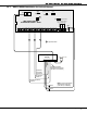
+ -+
-
Black
Red
S
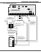
Alternate Alarm
Combo Alarm
Auxiliary Power In
+ Signal Voltage In
+ To Remote Receiver
- To Remote Receiver
- Signal Voltage In
EARTH GROUND
GROUND
GROUND
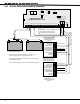
Up to 60 hours of battery standby time can be supplied using two 7.0 Ah,
sealed, Lead-Acid batteries.
All modules must be installed in a Model 340FC, 340SL, 349, or 350
Enclosure connected by no more than 20 feet of conduit.
This configuration transmits alarm and trouble signals only and does not
transmit Supervisory signals.
For complete system reports, use the 2-line dialer capability of the panel.
Reversing Relay Module
Radionics Model D127
5mA Standby, 55mA Alarm
@12 VDC
Alternate Alarm
Combo Alarm
Auxiliary Power In
+ Signal Voltage In
+ To Remote Receiver
- To Remote Receiver
- Signal Voltage In
EARTH GROUND
GROUND
GROUND
Reversing Relay Module
Radionics Model D127
5mA Standby, 55mA Alarm
@12 VDC
S
To Telephone Line
To Telephone Line
S
= Supervised Circuit
Intended for connection to a
polarity reversal circuit of a
remote station receiving unit
having compatible ratings.
S
S
S
Fire Trouble Output 2
Fire Alarm Output 1
Note: Output 1 must be programmed as a Fire
Alarm Output and Output 2 must be
programmed as a Fire Trouble Output.