
Installation guide


XR5 Installation Guide Digital Monitoring Products
17
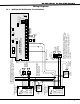
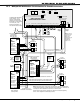
WIRING DIAGRAMS
21.3 Multiple 866 NotiÞ cation Circuit Modules for Zoned Annunciation
AC
1
3
+B
5
BELL
6
SMK
11
Z1A+
7
RED
8
YEL
9
GRN
10
BLK
2
AC
4
-B
12
Z1A-
13
Z1B+
14
Z1B-
15
Z2+
16
Z2-
17
Z3+
18
Z3-
19
Z4+
20
Z4-
21
Z5+
22
Z5-
N/ON/C COMN/ON/C COM
J11
1
2
3
4
J12
OUTPUT 2
OUTPUT 1
MAIN
BACKUP
Telephone
Connections
J4 J5
Silence/Reset
Header
J13
J14
Bell
Monitor
Silence/Reset
Button
Silence/Reset
Push for 1 Second
Panel
Reset
J10 Trouble Annunciator Header
Relay Sockets for Optional
Form C Outputs on J11
XR5 Commercial Fire
Command Processor™ Panel
S
S
3.3K EOL
Zone 2
SS
W
W
Zone 1
SS SS
3.3K EOL
Zone 3
SS
3.3K EOL
Zone 3
SS
Power Supply Trouble
Contacts N/C
To additional 866 Notification
Circuit Modules. Up to a
maximum of thirteen 866
Modules on the XR5 panels.
All modules must be installed
in a 340FC, 349, or 350
Enclosure connected by no
more than 20 feet of conduit.
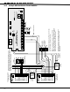
S
= Supervised Circuit
1 AUX PWR
2 GND
3 Alarm In
4 Bell PWR In
5 Bell Out +
6 Bell Out -
7 Bell Trouble
8 Bell Trouble
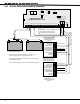
866
Module
Normal/Silence Switch
Zone 1 Notification
Circuit Module
DMP Model 866
45mA @12 VDC
10K EOL
DMP Model 308
S
S
Note: If an auxiliary power supply is not used, terminals 3 and 4 on the 866 Module
can be jumpered together to receive Bell Power from the XR5F panel. A maximum of
1.5 Amps as 12 VDC is available from terminal 5 of the XR5F panel.
Auxiliary Power Supply must be regulated, UL Listed for Fire Protective Signaling
Service. Power Supplies must have battery backup.
1 AUX PWR
2 GND
3 Alarm In
4 Bell PWR In
5 Bell Out +
6 Bell Out -
7 Bell Trouble
8 Bell Trouble
866
Module
Normal/Silence Switch
Zone 2 Notification
Circuit Module
DMP Model 866
45mA @12 VDC
24 VDC 5
Amp
Maximum
+ -
Auxiliary
Power
Supply
10K EOL
DMP Model 308
S
S
1 AUX PWR
2 GND
3 Alarm In
4 Bell PWR In
5 Bell Out +
6 Bell Out -
7 Bell Trouble
8 Bell Trouble
866
Module
Normal/Silence Switch
Notification Circuit Module
DMP Model 866
45mA @12 VDC
10K EOL
DMP Model 308
S
S
To additional Zone 2
Notification Circuit Modules
S
24 VDC 5
Amp
Maximum
+ -
Auxiliary
Power
Supply
24 VDC 5 Amp
Maximum
+ -
Auxiliary
Power
Supply
S
S
S
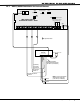
Output 1
Normally Open
Output 2
Normally Open
Zone 1
Output
Zone 2
Output
Note: In order to
activte the proper
relay, the zone
alarm action
programming must
be selected to
activate relay
ouputs 1 or 2.
A maximum of 1.5 Amps is available from terminal 5 of
the XR5FC.
Each 866 Notification Appliance Circuit Module in alarm
draws up to 59mA through its Terminal 3 Alarm Input.