
Installation guide


XR5 Installation Guide Digital Monitoring Products
13
INSTALLATION
14.3 NotiÞ cation
Registered terminal equipment must not be repaired by the user. In case of trouble, the device must be
immediately unplugged from the telephone jack. The factory warranty provides for repairs. Registered
terminal equipment may not be used on party lines or in connection with coin telephones. No tiÞ cation
must be given to the telephone company of:
a. The particular line(s) the service is connected to
b. The FCC registration number
c. The ringer equivalence
d. The make, model, and serial number of the device
Reset Jumper J9
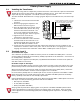
15.1 Description
There is a reset jumper located at the top right of the panel’s circuit board labeled RESET. Momentarily
shorting the metal wires of the jumper with a screwdriver allows you to reset the microprocessor of the
XR5FC and XR5SL panels, allowing you to enter the internal Programmer.
You can reset the panel while the system is operational (for example, during a service call) without
powering down the system.
After resetting the panel for programming, you must begin within 30 minutes. If you wait longer than 30
minutes, you will have to reset the panel again.
Silence/Reset Button
16.1 Silence/Reset Button
The XR5FC and XR5SL panels each contain a mechanical push button located on the top center of the
printed circuit board that allows authorized users to silence alarm bells or sirens and reset latched
detection devices.
After pressing the button, the panel silences the Bell output (XR5FC terminal 5) and momentarily drops
power to the auxiliary output (XR5FC terminal 6), the 377 Trouble Annunciator Module, and zones 2 to 5
(both panels). Additionally, any Fire or Supervisory event displays at the keypads are also cleared. A 2-pin
reset header (J13) is also provided for use with keyswitches.
16.2 Bell Circuit Monitor
The XR5FC panel contains a bell monitor input (J14) that can be connected to the trouble contacts of
the Model 865 or 866 NotiÞ cation Circuit Module. When the 2-pin header is shorted via the notiÞ cation
module, the Bell Circuit Monitor is in a restored condition. When the trouble contacts open, a bell circuit
trouble is indicated. The XR5FC is shipped from the factory with a shorting clip on the 2-pin header to
indicate a restored condition. The DMP Model 306 harness is used to connect the J14 Bell Circuit Monitor to
the trouble contacts of the 865 or 866 NotiÞ cation Circuit Module.
Dual Phone Line Connectors
17.1 Description
The XR5FC and XR5SL panels contain built-in dual phone line capability that allows the panel to monitor
two phone lines, indicate a phone line failure, and switch to the alternate phone line to communicate
alarm and system reports to a central station.
Before sending a report, the panel veriÞ es whether the main phone line is working. If not, the panel sends
the report over the backup phone line. An integrated phone line monitor circuit continually tests the
phone lines and indicates a trouble condition on the line after 90 seconds. If the phone line restores and is
good for 90 seconds, the panel ends the phone line trouble indication.