
Installation guide


Digital Monitoring Products XR5 Installation Guide
8
INSTALLATION
Secondary Power Supply
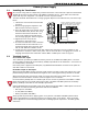
6.1 Battery Terminals 3 and 4
Connect the black battery lead to terminal 4 on the panel and then to the negative terminal of the battery.
The negative terminal connects to the enclosure ground internally through the XR5FC and XR5SL panel
circuit board. Connect the red battery lead to terminal 3 on the panel and then to the positive terminal of
the battery. Observe polarity when connecting the battery.
The XR5FC and XR5SL panels are capable of recharging two 7.0 Ah batteries (14 Amp/hours) within 24
hours.
Do not use battery backup with 24 VDC input: Do not connect batteries to the XR5FC and XR5SL panels
when powering the panels with 20 to 28.2 VDC voltage from a Fire Alarm Control Panel (FACP). The XR5FC
and XR5SL panels use the backup battery capability of the FACP for their standby requirements.
Use sealed lead-acid batteries only: Use the DMP Model 367, 12 VDC 7.7 Ah or Model 369 7.0 Ah sealed
lead-acid rechargeable battery. Batteries supplied by DMP or manufactured by Eagle Picher or Yuasa have
been tested to ensure proper charging with DMP products.
DO NOT USE GEL CELL BATTERIES WITH THE XR5FC AND XR5SL.
6.2 Earth Ground
Terminal 4 of the XR5FC and XR5SL panels must be connected to earth ground using 14 gauge or larger wire
to provide proper transient suppression. DMP recommends connecting to a metal cold water pipe or ground
rod only. Do not connect to electrical conduit or a telephone company ground.
6.3 Replacement Period
DMP recommends replacing the battery every 3 to 5 years under normal use.
6.4 Discharge/Recharge
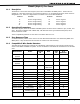
The battery charging circuit on the XR5FC and XR5SL panels ß oat charge at 13.9 VDC at a maximum current
of 1.2 Amps using the Model 320 Transformer. The total current available is reduced by the combined
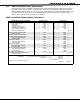
auxiliary current draw from terminals 6, 7, 15, 17, 19, and 21. The various battery voltage levels are listed
below:
Battery Trouble: Below 11.9 VDC
Battery Restored: Above 12.6 VDC
6.5 Battery Supervision
The XR5FC and XR5SL panels load test the battery once every three minutes when AC power is present on
terminal 1 and 2. The test lasts for Þ ve seconds. If, during the test, the battery voltage falls below 11.9
VDC a low battery is indicated. The test is then repeated every two minutes until the battery charges
above 12.6 VDC, the battery restored voltage.
If the low battery does not recharge and is replaced with a fully charged battery, the charged battery will
not be detected until the next two minute test is done.
If AC power fails during normal system operation, a low battery is indicated any time the battery voltage
falls below 11.9 VDC.