
Installation guide


XR5 Installation Guide Digital Monitoring Products
7
INSTALLATION
Primary Power Supply
5.1 Installing the Transformer
All electrical wiring must be completed by a trained electrician! The transformer requires an unswitched
120 VAC 60 Hz electrical outlet with at least 350mA of available current. Never share the transformer
output with any other equipment. The 120 VAC circuit is not power limited.
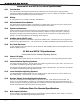
To mount the Model 320 Transformer to a single-gang box adjacent to the XR5 enclosure, follow the steps
below.
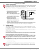
1. Remove the lower knockout from the XR5
enclosure.
2. Attach a single-gang box adjacent to the
XR5 enclosure as shown in Figure 6.
3. After the single-gang box is secured, attach
the transformer to the junction box, using
the bottom box’s bottom knockout. The
screw on the transformer should extend
into the single-gang box. Refer to Figure 6.
4. Tighten the screw to secure the
transformer to the junction box .
5. An electrician must then connect the black
and white leads on the transformer to an
unswitched 120 VAC 60 Hz electrical outlet
with at least 350mA of available current.
6. Connect the wires from the bottom (the side opposite the attaching screw) two terminals on the
transformer to terminals 1 and 2 on the panel. Use no more than 70 ft. of 16-gauge wire or 40 ft. of
18-gauge wire between the transformer and the XR5FC or XR5SL panel. Refer to Figure 6.
5.2 Terminals 1 and 2
AC Transformer Input
The transformer provides up to 500mA of auxiliary current for the XR5FC and XR5SL panels. The total
current available is limited by the total battery standby requirements of the installation. See section 6.6
for standby battery calculations.
Note: After power is applied to the XR5 panel, any 866 NotiÞ cation Modules connected to the panel will
show Bell Trouble for 20 seconds.
DC Power Input to AC Input
When powering the XR5FC/SL panel from the 12 VDC output of an FACP, connect the positive wire to the
positive battery terminal of the XR5 and the negative wire to the negative battery terminal of the XR5.
When powering the panel from the DC output of a 24 Volt Fire Alarm Control Panel (FACP), connect the
positive wire from the FACP to terminal 1 and the negative wire to terminal 2.
Do not use battery backup with 12 or 24 VDC input: Do not connect any batteries to the XR5FC or XR5SL
panels when using the 12 or 24 VDC output from a FACP. The XR5FC and XR5SL panels use the backup
battery capability of the FACP for their standby requirements.
Features disabled when using 24 VDC power input: When powering the XR5FC or XR5SL panel from the 24
VDC output of a FACP, the following operational features are disabled:
• Bell Output on the XR5FC
• AC test (XR5FC and XR5SL)
• Battery test (XR5FC and XR5SL)
Always ground the panel before applying power to any devices: The XR5FC and XR5SL panels must be
properly grounded before connecting any devices or applying power to the panels. Proper grounding
protects against Electrostatic Discharge (ESD) that can damage system components. See Earth ground,
section 6.2.
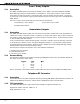
Wiring on terminals 7 through 22 must exit
to the right and maintain a 1/4" separation
from the AC and battery positive wiring.
Figure 6: Transformer Installation