
Installation guide


Digital Monitoring Products XR5 Installation Guide
6
INSTALLATION
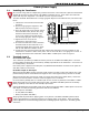
4.3 Mounting Keypads
Security Command keypads have removable covers that allow you to easily mount the base to a wall or
other ß at surface. After installing the keypad mounting anchors and bringing the keypad wiring from the
panel through the wall, mount the base and connect the keypad wire harness leads to the keypad wiring.
Next, attach the keypad wire harness connector to the pin connector on the keypad circuit board and
install the cover.
For mounting keypads on masonry walls, or for applications where conduit is required, use an appropriate
DMP keypad conduit backbox.
4.4 Wiring SpeciÞ cations
1. You can install individual keypads on wire runs of up to 500 feet using 22 gauge wire or up to 1,000 feet
using 18 gauge wire. To increase the wire length or add additional devices, a power supply is required.
2. Maximum distance for any one keypad bus circuit (length of wire) is 2,500 feet regardless of the gauge
of wire. This distance can be in the form of one long wire run or multiple branches with all wiring
totaling no more than 2,500 feet.
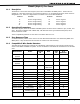
3. Maximum number of devices per 2,500 feet circuit is 40. (Refer to the section 9.1 for the speciÞ c
number of supervised keypads that are allowed.)
4. Maximum voltage drop between the panel (or auxiliary power supply) and any device is 2.0 VDC. If the
voltage at any device is less than the required level, an auxiliary power supply should be added at the
end of the circuit.
Refer to the wiring diagram in section 3.2 in this guide for additional wiring information. For more
information, refer to the 710 Module Installation Sheet (LT-0310). Also see the Trouble-Free LX-Bus/Keypad
Bus Wiring Application Note (LT-2031).
Note: Do not use shielded wire for the keypad bus.
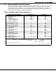
4.5 Terminal Wiring Connections
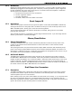
In all applications where more than one wire is under a terminal, the wire must be cut and not looped
around the screw terminal. See Figure 5.
Figure 5: Wiring Connections