
Installation guide


Digital Monitoring Products XR5 Installation Guide
4
INTRODUCTION
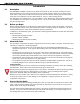
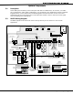
3.3 XR5SL Wiring Diagram
The XR5SL system below shows some of the accessory devices you can connect for use in various
applications.
AC
1
3
+B
5
BELL
6
SMK
11
Z1A+
7
RED
8
YEL
9
GRN
10
BLK
2
AC
4
-B
12
Z1A-
13
Z1B+
14
Z1B-
15
Z2+
16
Z2-
17
Z3+
18
Z3-
19
Z4+
20
Z4-
21
Z5+
22
Z5-
N/ON/C COMN/ON/C COM
J11
1
2
3
4
J12
OUTPUT 2
OUTPUT 1
MAIN
BACKUP
Telephone
Connections
J4 J5
Silence/Reset
Header
J13
Bell
Monitor
J14
Silence/Reset
Button
Silence/Reset
Push for 1 Second
Panel
Reset
J10 Trouble Annunciator Header
Relay Sockets for Optional
Form C Outputs on J11
RED
BLACK
GREEN
Up to 500mA auxiliary current at 12 VDC from terminal 7
BLACK
YELLOW
RED
Cold Water Pipe
Earth Ground
Output Header J11
Two Form C (SPDT) Outputs.
Zone 2
Output Header J12
Four Open Collector Outputs.
50mA at 30 VDC resistive
Uses Model 300 Harness
Zone
1
M
M
Keypad
Model 690
Direct connect to
unswitched 120 VAC 60 Hz
Secondary Power Supply
Model 367 or 369 Battery 12 VDC
1.2 Amps Max. charging current.
Up to 500mA auxiliary
current at 12 VDC from
Terminal 7.
32-Character Keypads
10 Zone LED Keypads
Zone 5
Keypad
Model 692F
30mA at 8 to 16 VDC.
Output 1 Output 2
W
W
Zone 3
S
S
Model 377
Trouble
Annunciator
Module
Model 320
16.5 VAC 40 VA
wire-in transformer
3.3k Ohm
Resistor
Model 309
Zone 3
H
S
16-Character Keypads
Keypad
Model 770
100mA at 8 to 16 VDC.
For sprinkler
supervision,
Normally Open
devices must be
used.
Zone 2
3.3 K Ohm
Zone 4
3.3 K Ohm
Zone 3
3.3 K Ohm
Al outputs must be
connected to devices
located within the same
room as the panel.
Heat detectors, pull stations, or any other contact devices
listed for Fire Protective Signaling can be connected to zones
1 to 5.
Zones 2 to 5 compatibility identifier: A
Maximum operating range: 8.8 to 14.2 VDC.
S
S
S
SS S S
S S
S S
S
S
= Supervised Circuit
Figure 2: XR5SL Wiring Diagram
3.4 Lightning Protection
Metal Oxide Varistors and Transient Voltage Suppressors on the panel help protect against voltage surges on
input and output circuits of the XR5 panels. Additional surge protection is available by installing the DMP
370 or 370RJ Lightning Suppressors.
3.5 Security Command® Keypads
You can connect the Models 690, 690F, 692F, 770, 771, 790, 790F, 791, or 793 Security Command keypads to
the 4-wire keypad bus provided by the panel on terminals 7, 8, 9, and 10.
Do not use shielded wire for the keypad bus.