INSTALLATION GUIDE XR5FC AND XR5SL COMMERCIAL FIRE PANELS
MODEL XR5FC/XR5SL COMMAND PROCESSOR INSTALLATION GUIDE FCC NOTICE This equipment generates and uses radio frequency energy and, if not installed and used properly in strict accordance with the manufacturer’s instructions, may cause interference with radio and television reception.
TABLE OF CONTENTS Revisions to This Document Panel SpeciÞcations 1.1 1.2 1.3 1.4 1.5 1.6 1.7 Power Supply ......................................................................... 1 Communication ...................................................................... 1 Panel Zones ........................................................................... 1 Remote Annunciators (Alphanumeric or LED Keypads) .............. 1 Auxiliary Outputs....................................................................
TABLE OF CONTENTS Class A (Style D) Fire Zone 10.1 Description ...........................................................................10 Class B (Style A) Fire Zones 11.1 11.2 11.3 11.4 Description ...........................................................................11 Operational Parameters .........................................................11 Zone Response Time .............................................................11 Compatible 2-Wire Smoke Detectors .............................
TABLE OF CONTENTS This page has been intentionally left blank.
REVISIONS Revisions to This Document This section explains the changes that were made to this document during this revision. This section lists the date the change was made, the section number and section heading, and a quick summary of the change. Date Section Number and Heading Quick Explanation of Changes 4/04 Sections 3.2, 3.3, and 6.1 Sections 3.5 and 6.6 Added battery model 369. Added keypad models 690F and 790F.
INTRODUCTION Panel SpeciÞcations 1.1 Power Supply Primary Power Input: 16.5 VAC 40 VA (Model 320 wire-in) or 12/24 VDC from Fire Alarm Control Panel (FACP) Standby Batteries: One or two 12 VDC 7.0 Ah Auxiliary Output: 500mA at 12 VDC Bell Output: 1.5 Amps at 12 VDC (XR5FC only) Smoke Detector Output: 100mA at 12 VDC (XR5FC only) All circuits inherent power limited except the red battery wire. 1.2 Communication Built-in SDLC Digital Dialer communication to DMP Model SCS-1 and SCS-1R Receivers.
INTRODUCTION Introduction 2.1 Description The DMP XR5FC and XR5SL Commercial Fire Panels are powerful 12 VDC Þre alarm communicators with battery backup that can also be powered from the 12 or 24 VDC auxiliary output of a Fire Alarm Control Panel (FACP). Each panel provides one Class A (Style D) Þre zone and four Class B (Style A) powered Þre zones with reset capability for 2-wire smoke detectors, relays, or other latching devices.
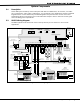
INTRODUCTION System Components 3.1 Description A basic XR5 system is made up of the alarm panel with built-in communicator, an enclosure, a 16.5 VAC wire-in transformer, and a 12 VDC 7.0 Ah battery. You can add up to two alphanumeric Security Command keypads and one or more LED Security Command keypads to the panel and also connect control and annunciating devices to the panel’s Form C and annunciator outputs. Refer to section 6.6 in this guide when calculating power requirements. 3.
INTRODUCTION 3.3 XR5SL Wiring Diagram The XR5SL system below shows some of the accessory devices you can connect for use in various applications.
INSTALLATION Installation 4.1 Mounting the Enclosure The metal enclosure for the XR5FC and XR5SL panels must be mounted in a secure, dry place to protect the panels from damage due to tampering or the elements. It is not necessary to remove the XR5FC or XR5SL PC board when installing the enclosure. 3/4" x 1/2" Knockout Two 1 3/4" Wire Openings 3/4" x 1/2" Knockouts Transformer Knockout Extra Deep 3 3/4" Cabinet Figure 3: Mounting the Enclosure 4.
INSTALLATION 4.3 Mounting Keypads Security Command keypads have removable covers that allow you to easily mount the base to a wall or other ßat surface. After installing the keypad mounting anchors and bringing the keypad wiring from the panel through the wall, mount the base and connect the keypad wire harness leads to the keypad wiring. Next, attach the keypad wire harness connector to the pin connector on the keypad circuit board and install the cover.
INSTALLATION Primary Power Supply 5.1 Installing the Transformer All electrical wiring must be completed by a trained electrician! The transformer requires an unswitched 120 VAC 60 Hz electrical outlet with at least 350mA of available current. Never share the transformer output with any other equipment. The 120 VAC circuit is not power limited. To mount the Model 320 Transformer to a single-gang box adjacent to the XR5 enclosure, follow the steps below. Wiring on terminals 7 through 22 must exit 1.
INSTALLATION Secondary Power Supply 6.1 Battery Terminals 3 and 4 Connect the black battery lead to terminal 4 on the panel and then to the negative terminal of the battery. The negative terminal connects to the enclosure ground internally through the XR5FC and XR5SL panel circuit board. Connect the red battery lead to terminal 3 on the panel and then to the positive terminal of the battery. Observe polarity when connecting the battery. The XR5FC and XR5SL panels are capable of recharging two 7.
INSTALLATION 6.6 XR5FC and XR5SL Power Requirements During AC power failure, the XR5FC and XR5SL panels, and all auxiliary devices connected to the panels, draw their power from the battery. All devices must be taken into consideration when calculating the battery standby capacity. Below is a list of the power requirements of the XR5FC and XR5SL panels.
INSTALLATION Bell Output 7.1 Terminal 5 (XR5FC Only) Terminal 5 supplies 12 VDC Bell Output to power alarm bells or horns. The output is rated for a maximum of 1.5 Amps. This output can be steady or pulsed depending upon the Bell Action speciÞed in Output Options programming. Terminal 10 is the ground reference for terminal 5. 4-Wire Smoke Detector Power 8.1 Terminal 6 (XR5FC Only) Terminal 6 provides up to 100mA at 12 VDC to power 4-wire smoke detectors or other auxiliary powered devices.
INSTALLATION Class B (Style A) Fire Zones 11.1 Description Terminals 15 to 22 are the Class B (Style A) Þre zones on the XR5FC and XR5SL panels. These zones are suitable for connecting powered or non-powered Þre devices. For programming purposes, these zones are designated 2 to 5. The zone conÞgurations on terminals 15 to 22 are described below: Terminal Function 15 17 19 21 11.
INSTALLATION Form C Relay Outputs 12.1 Description The XR5FC and XR5SL panels can provide two auxiliary Form C (SPDT) relays when equipped with DMP Model 305 Plug-in Relays in sockets OUTPUT 1 and OUTPUT 2. Each relay is rated for 1 Amp at 30 VDC. Each output provides one Common, one Normally Open, and one Normally Closed terminal. Field wiring for the Form C relays connects to the 6-position terminal strip on the lower right corner of the XR5FC and XR5SL boards.
INSTALLATION 14.3 NotiÞcation Registered terminal equipment must not be repaired by the user. In case of trouble, the device must be immediately unplugged from the telephone jack. The factory warranty provides for repairs. Registered terminal equipment may not be used on party lines or in connection with coin telephones. NotiÞcation must be given to the telephone company of: a. b. c. d.
COMPLIANCE Universal UL and NFPA Fire Alarm SpeciÞcations 18.1 Introduction The programming and installation speciÞcations contained in this section must be completed when installing the XR5FC and XR5SL panels in accordance with any of the UL or NFPA Þre standards. Additional speciÞcations may be required by a particular standard. 18.2 Wiring All wiring must be in accordance with NEC, ANSI/NFPA 70. 18.
1 2 3 4 5 6 7 8 AUX PWR GND Alarm In Bell PWR In Bell Out + Bell Out Bell Trouble Bell Trouble 866 Module Normal/Silence Switch Notification Circuit Module DMP Model 866 45mA @12 VDC Power Supply Trouble Contacts N/C + Auxiliary Power Supply AUX PWR GND Alarm In Bell PWR In Bell Out + Bell Out Bell Trouble Bell Trouble 24 VDC 5 Amp Maximum 1 2 3 4 5 6 7 8 866 Module Normal/Silence Switch Notification Circuit Module DMP Model 866 45mA @12 VDC S UL Listed, Polarized Notification Appliances 24 V
Normal/Silence Switch + Auxiliary Power Supply Notification Circuit Module DMP Model 865 25mA @12 VDC 1 AUX PWR 2 GND 3 Alarm In 4 Bell PWR In + 5 Bell PWR In 6 Bell Out A + 7 Bell Out A 8 Bell Out B + 9 Bell Out B 10 Bell Trouble 11 Bell Trouble 865 Module Normal/Silence Switch Power Supply Trouble Contacts N/C 24 VDC 5 Amp Maximum 1 AUX PWR 2 GND 3 Alarm In 4 Bell PWR In + 5 Bell PWR In 6 Bell Out A + 7 Bell Out A 8 Bell Out B + 9 Bell Out B 10 Bell Trouble 11 Bell Trouble 865 Module S Style Y
WIRING DIAGRAMS 21.
WIRING DIAGRAMS 21.
WIRING DIAGRAMS 21.
WIRING DIAGRAMS XR5SL Connection to FACP MAIN BACKUP J4 AC Mode Wiring When the XR5SL is used in the AC Mode, the DMP Model 320 Transformer must be connected to the same branch circuit as the FACP.
WIRING DIAGRAMS 21.
LT-0299 (4/04) © 2004 Digital Monitoring Products, Inc. 800-641-4282 INTRUSION • FIRE • ACCESS • NETWORKS www.dmp.