
User Manual

888-996-2729 - 1 l l a C e c i v r e S r e m o t s u C r o F 6s t r o p S e d a l a c s E 140 2 ©
All Rights Reserved
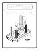
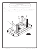
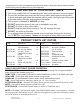
STEP 3:
With the help of another adult, carefully lift and rotate table into upright position.
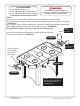
First, feed the sensor plug from each Goalflex80 Goal P5 through each end apron as shown
in FIGURE 3A.
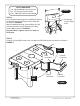
Next, use pilot holes provided to attach each Goalflex80 Goal P5 using Phillips Round Head
Screws H3 and Phillips Round Head Screws H4 as shown in FIGURE 3B.
Important Note: Tighten, but do not strip out H3 and H4 Screws.
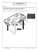
Next, feed the plugs through underneath support beams and through
long side apron as shown in FIGURE 3C.
FIGURE 3A
THIS STEP REQUIRES TWO OR MORE ADULTS.
VERY CAREFULLY TURN THE TABLE OVER AND SET IT ON
ITS LEGS. BE CAREFUL, THE TABLE IS HEAVY.
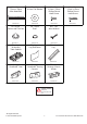
PARTS REQUIRED:
2 pcs - P5 Goalflex80 Goal
6 pcs - H3 Phillips Round Head Screw
4 pcs - H4 Phillips Round Head Screw
H3
H4
Feed the sensor
plug from P5
through the
end apron.
FIGURE 3B
NOTE: Do not discard wire
ties as they can be used
under table to secure
hanging wires.
FIGURE 3C
NOTE:
Use H4 Screws
this location.
NOTE:
Use H3 Screws
this location.
P5
P5