
Specifications

G0
57QN01 V2 Ver. 1.0
17/25
G057QN01 V2
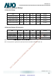
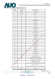
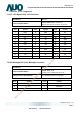
6.6 LED Backlight Unit Interface Signal Description
Pin # Symbol Pin Description
1 V
LED
12V input
2 V
LED
12V input
3 GND Ground
4 GND Ground
5 PWM DIM 1~100% PWM dimming
6 LED On/Off 0V-Off; 3.3~5V/NC-On
Note 1: “NC” stands for ”No Connection
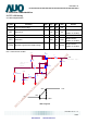
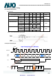
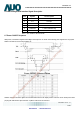
6.7 Power ON/OFF Sequence
VDD power, LCD interface signals and backlight on/off sequence are shown in the following chart. Signals from any system
shall be Hi-Z state or low level when VDD is off.
Power ON/OFF sequence timing
ON/OFF sequence should be applied to avoid abnormal function in the display. Please make sure to turn off the power when
you plug the cable into the input connector or pull the cable out of the connector.
AUO Confidential For DATAMODUL Internal Use Only / 2011/12/2
Data Modul AG - www.data-modul.com