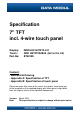
Specification 7" TFT incl. 4-wire touch panel Display: Touch: Part-No: INNOLUX G070Y2-L01 DMC AST070A080A (tail to the left) BT63189 Content: - Mechanical Drawing - Appendix A: Specification of TFT - Appendix B: Specification of touch panel Please be aware that some of the values e.g. optical, mechanical etc. of the complete unit (assembled display plus touch panel) might differ from the original values of the individual components.
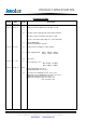
1 2 3 4 5 6 7 8 168,2 ±0,5 165 ±0,3 (Outline Touch) A 11,06 83,3 2 2,4 A 1,4 ±0,2 2,1 78 10,5 152,4 ( A-A -Display+Touch) 154,9 (V-A-Touch) C 2 2,05 C B 104 ±0,3(Outline Touch) 3,8 104 ±0,3 (Outline Display) 108 ±0,5 Center of active area 55,32 16 1 B Inside the dotted zone do not press to seal. 93,94 ( V-A-Touch) 4 Contact (front) 91,44 (A-A-Display+Touch) 2,4 6,25 2 Air Vent No pressure on the air vent area ! 3,1 POS-NR.
Specification G070Y2-L01 17.8cm (7.0") / WVGA / LVDS / LED Version: 2.
PRODUCT SPECIFICATION Doc. Number : □ Tentative Specification □ Preliminary Specification ■ Approval Specification MODEL NO.: G070Y2 SUFFIX: L01 Customer: APPROVED BY SIGNATURE Name / Title Note Please return 1 copy for your confirmation with your signature and comments. 核准時間 部門 審核 角色 投票 2011-08-24 16:09:06 APPL 產品管理處 yuhsiang.chang (張喻翔/514-10922) Director Accept Version 2.4 23 August 2011 The copyright belongs to CHIMEI InnoLux. Any unauthorized use is prohibited. Data Modul AG - www.
PRODUCT SPECIFICATION - CONTENTS REVISION HISTORY ------------------------------------------------------- 3 1.
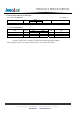
PRODUCT SPECIFICATION REVISION HISTORY Version Date Section Description Ver 2.0 Oct. 30, ‘09 All G070Y2-L01 Approval specification was first issued. Ver 2.1 May.13, 10 1.4 Module Power Consumption from 3.56 W to 3.71 W 3.2 Converter Power Supply Current from 0.25A to 0.263mA Converter Power Consumption from 3W to 3.15W Note(2) IL = 60 mA(Per EA) change to IL = 55 mA(Per EA) Ver 2.2 Sep. 9, 10 Ver 2.3 Dec. 1, 10 7.1 TEST CONDITIONS Current from 60±4mA to 55±3mA 1.
PRODUCT SPECIFICATION 1. GENERAL DESCRIPTION 1.1 OVERVIEW G070Y2-L01 is a 7inch TFT Liquid Crystal Display module with a LED backlight unit and a-20pin 6/8bit LVDS interface controller board. The converter for the LED Backlight Unit is built in. This module supports 800 (R.G.B )x 480 WVGA mode which main application is the automotive display and industrial field. 1.2 FEATURES - Wide viewing angle.
PRODUCT SPECIFICATION Note (2) 1.5 MECHANICAL SPECIFICATIONS Item Horizontal (H) Module Size Vertical (V) Depth (D) Weight Min. 164.3 103.3 9.03 Typ. 165 104 9.53 147 Max. 165.3 104.3 10.03 162 Unit mm mm mm g Note (1) Note (1) Please refer to the attached drawings for more information of front and back outline dimensions. Version 2.4 23 August 2011 The copyright belongs to CHIMEI InnoLux. Any unauthorized use is prohibited. Data Modul AG - www.data-modul.
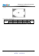
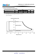
PRODUCT SPECIFICATION 2. ABSOLUTE MAXIMUM RATINGS 2.1 ABSOLUTE RATINGS OF ENVIRONMENT Item Value Symbol Operating Ambient Temperature Storage Temperature Min. -30 -40 TOP TST Unit Max. +85 +95 Note ºC ºC Note (1) Temperature and relative humidity range is shown in the figure below. (2) Wet-bulb temperature should be 39 ºC Max. (Ta > 40 ºC). (3) No condensation.
PRODUCT SPECIFICATION 2.2 ELECTRICAL ABSOLUTE RATINGS 2.2.1 TFT LCD MODULE Item Ta = 25 ± 2 ºC Symbol Power Supply Voltage Vcc Value Min. -0.3 Max. 4 Unit Note V (1) 2.2.2 LED CONVERTER Item Symbol Converter Voltage Enable Voltage Backlight Adjust Vi EN ADJ Value Min. -0.3 ----- Max. 18 5 5 Unit Note V V V (1) , (2) Note (1) Permanent damage to the device may occur if maximum values are exceeded.
PRODUCT SPECIFICATION 3. ELECTRICAL CHARACTERISTICS 3.1 RECOMMENDED OPERATION CONDITION Parameter Symbol Power Supply Voltage Rush Current Min. 3.0 Vcc IRUSH White Black LVDS Differential Input High Threshold LVDS Differential Input Low Threshold LVDS Common Mode Voltage Ta = 25 ± 2 ºC Value Typ. Max. 3.3 3.6 1.5 250 270 100 Power Supply Current VTH(LVDS) VTL(LVDS) VCM -100 1.2 Unit Note V A mA mA mV mV V (1) (2) (3)a (3)b - Note (1) The assembly should be always operated within above ranges.
PRODUCT SPECIFICATION Note (3) The specified power supply current is under the conditions at Vcc = 3.3V , Ta = 25 ± 2 ºC, fv = 60 Hz, whereas a power dissipation check pattern below is displayed. a. White Pattern b. Black Pattern Active Area Active Area Version 2.4 23 August 2011 The copyright belongs to CHIMEI InnoLux. Any unauthorized use is prohibited. Data Modul AG - www.data-modul.
PRODUCT SPECIFICATION 3.2 BACKLIGHT UNIT Ta = 25 ± 2 ºC Parameter Symbol Value Typ. 12.0 Max. 13.2 Unit Converter Power Supply Voltage Vi Min. 10.8 Converter Power Supply Current Ii --- 0.263 --- A PLED --- 3.15 --- W --------- fPWM 2.0 0 2.0 0 10 100 5 0.8 5 0.
PRODUCT SPECIFICATION 4. BLOCK DIAGRAM 4.1 TFT LCD MODULE SCAN DRIVER IC VCC_IN INPUT CONNECTOR (076B20-0048RA-G4,Starconn) RX3(+/-) FRC RX2(+/-) RXC(+/-) RX1(+/-) RX0(+/-) LR UD LVDS Receiver INPUT TFT LCD PANEL (800x R.G.B.x480) DATA DRIVER IC DC/DC CONVERTER & REFERENCE VOLTAGE GND Vi Version 2.4 CONVERTER CONNECTOR (LM123S004HTF13) LED Converter LED BACKLIGHT UNIT 23 August 2011 The copyright belongs to CHIMEI InnoLux. Any unauthorized use is prohibited. Data Modul AG - www.data-modul.
PRODUCT SPECIFICATION 5. INPUT TERMINAL PIN ASSIGNMENT 5.1 LVDS I/O PIN ASSIGNMENT Pin Name I/O 1 RX3+ I 2 RX3- I 3 NC I 4 FRC I 5 GND I 6 RXC+ I 7 RXC- I 8 GND I 9 RX2+ I 10 RX2- I 11 GND I 12 RX1+ I 13 RX1- I 14 GND I 15 RX0+ I 16 RX0- I Description LVDS differential data input Pair 3.
PRODUCT SPECIFICATION 5.3 SCANNING DIRECTION The following figures show the image see from the front view. The arrow indicates the direction of scan. Fig.1 Normal Scan Fig.2 Reverse Scan Fig.3 Reverse Scan Fig.4 Reverse Scan Fig. 1 Normal scan ( pin 17, LR = High ; pin 18, UD = Low ) Fig. 2 Reverse scan ( pin 17, LR = Low ; pin 18, UD = Low ) Fig. 3 Reverse scan ( pin 17, LR = High ; pin 18, UD = High ) Fig. 4 Reverse scan ( pin 17, LR = Low ; pin 18, UD = High ) Version 2.
PRODUCT SPECIFICATION 5.4 COLOR DATA INPUT ASSIGNMENT The brightness of each primary color (red, green and blue) is based on the 6-bit gray scale data input for the color. The higher the binary input, the brighter the color. The table below provides the assignment of color versus data input.
PRODUCT SPECIFICATION The brightness of each primary color (red, green and blue) is based on the 8-bit gray scale data input for the color. The higher the binary input, the brighter the color. The table below provides the assignment of color versus data input.
PRODUCT SPECIFICATION 6. INTERFACE TIMING 6.1 TIMING CHARACTERISTICS The input signal timing specifications are shown as the following table and timing diagram Parameter Symbol Vertical Display Value Typ. 500 Max. 550 Unit Period Tv Min. 490 Active Blanking Tvd Tvb 10 480 20 70 Th Th Period Th 930 992 1090 Tclock Thd Thb 1/Tclock 130 28 800 192 29.
PRODUCT SPECIFICATION 6.2 LVDS INPUT DATA FORMAT Note (1) R/G/B data 7: MSB, R/G/B data 0: LSB Note (2) Please follow PSWG Note (3) Output signals from any system shall be low or Hi-Z state when VCC is off. Version 2.4 23 August 2011 The copyright belongs to CHIMEI InnoLux. Any unauthorized use is prohibited. Data Modul AG - www.data-modul.
PRODUCT SPECIFICATION 6.3 POWER ON/OFF SEQUENCE To prevent a latch-up or DC operation of LCD assembly, the power on/off sequence should be as the diagram below 0.9VCC VCC 0.9VCC 90% 0.1VCC 0.1VCC 10% T7 T1 T2 T3 VALID LVDS Vi T4 0.9Vi 0.9Vi 0.1Vi 0.1Vi T6 T5 90% PWM DIMMING 10% T8 T9 90% BL ON/OFF 10% Power ON/OFF sequence Note (1) Please avoid floating state of interface signal at invalid period.
PRODUCT SPECIFICATION 7. OPTICAL CHARACTERISTICS 7.1 TEST CONDITIONS Item Ambient Temperature Ambient Humidity Supply Voltage Input Signal Current Converter Duty Symbol Value Unit o Ta C 25±2 Ha %RH 50±10 VCC 3.3 V According to typical value in "3. ELECTRICAL CHARACTERISTICS" If mA 55±3 100 % Note (1) If means the forward current of each channel 7.2 OPTICAL SPECIFICATIONS The relative measurement methods of optical characteristics are shown in 7.2.
PRODUCT SPECIFICATION Note (1) Definition of Viewing Angle (θx, θy): Normal θx = θy = 0º θyθX- = 90º 12 o’clock direction xθx− 6 o’clock θy+ y+ θx+ θy+ = 90º y- x+ θy- = 90º θX+ = 90º Note (2) Definition of Contrast Ratio (CR): The contrast ratio can be calculated by the following expression. Contrast Ratio (CR) = L63 / L0 L63: Luminance of gray level 63 L 0: Luminance of gray level 0 CR = CR (5) CR (X) is corresponding to the Contrast Ratio of the point X at Figure in Note (5).
PRODUCT SPECIFICATION Note (4) Definition of Luminance of White (LC): Measure the luminance of gray level 63 at center point LC = L (5) L (x) is corresponding to the luminance of the point X at Figure in Note (5).
PRODUCT SPECIFICATION 8. RELIABILITY TEST 8.1 RELIABILITY TEST CONDITION No. Test Item Test Condition Note 1 High Temperature Storage 95℃, 240 hours 2 Low Temperature Storage -40℃, 240 hours 3 Thermal Shock Storage {(-40℃, 0.5 hour) (85℃, 0.5 hour)}, 100 cycles 4 High Temperature Operating 85℃, 240 hours 5 Low Temperature Operating -30℃, 240 hours 6 High Temperature & High Humidity Operating 60℃, 90% RH, 240hours (1) (2) 100G, 6ms, half sine wave, 3 times for ± X, ± Y, ± Z.
PRODUCT SPECIFICATION 9. PACKAGING Version 2.4 23 August 2011 The copyright belongs to CHIMEI InnoLux. Any unauthorized use is prohibited. Data Modul AG - www.data-modul.
PRODUCT SPECIFICATION Sea / Land Transportation (40ft Container) Version 2.4 Air Transportation 23 August 2011 The copyright belongs to CHIMEI InnoLux. Any unauthorized use is prohibited. Data Modul AG - www.data-modul.
PRODUCT SPECIFICATION 10. DEFINITION OF LABELS 10.1 CMO MODULE LABEL The barcode nameplate is pasted on each module as illustration, and its definitions are as following explanation. CHI E207943 MEI G070Y2 -L01 OPTOELECTRONICS Rev.XX MADE IN TAIWAN RoHS XXXXXXXYMDLNNNN (a) Model Name: G070Y2 -L01 (b) Revision: Rev. XX, for example: A1, …, C1, C2 …etc. (c) Serial ID: X X X X X X X Y M D X N N N N Serial No.
PRODUCT SPECIFICATION 11. PRECAUTIONS 11.1 ASSEMBLY AND HANDLING PRECAUTIONS (1) Do not apply rough force such as bending or twisting to the module during assembly. (2) To assemble or install module into user’s system can be only in clean working areas. The dust and oil may cause electrical short or worsen the polarizer. (3) It’s not permitted to have pressure or impulse on the module because the LCD panel and Backlight will be damaged.
Data Modul AG - www.data-modul.
Data Modul AG - www.data-modul.
Specification AST/ATP Series Revision 11 Version March 23, 2010 Data Modul AG - www.data-modul.
Table of Contents 1. Product Specifications ...........................................................................................................................3 1-1. Product Applicable .............................................................................................................................3 1-2. Structure.............................................................................................................................................3 1-3. Environmental Specifications .
1. Product Specifications 1-1. Product Applicable § This specification is applied to the analog resistive touchscreen: ATP/AST Series. 1-2. Structure § Dimensions, structure, and shape are referred on the drawing attached. 1-3. Environmental Specifications Specification Value Operating Temperature -20°C to 70°C (no condensation) Operating Humidity -20°C to 60°C Less than 90%RH (no condensation) 3 Exceeding 60°C 133.
1-6. Appearance § Scratch, dust (W = width, L = length, D = average diameter = (longest + shortest) /2) Item Width (mm) Length (mm) Acceptable Numbers Linear(Scratch/Dust) Over 0.1mm in diameter refer to the Circular. 0.1≥W>0.05 4≥L 1pcs in φ30mm 0.05≥W>0.03 10≥L 2pcs in φ20mm 0.03≥W 20≥L Acceptable Circular (Scratch/Dust) 0.4≥D>0.3 *1 1pcs in viewing area *1 0.3≥D>0.2 2pcs in φ30mm 0.2≥D Acceptable Total Within 5pcs /panel Applied only in the Active Area.
2. Testing Regulation 2-1. Testing Regulation § If the regulation is not specified, the test is performed under the supplier’s regulation. § Tests are performed under the room temperature unless specified. The room temperature is referred as follows: Temperature: 20°C±5°C Humidity: 65%±10%RH 2-2. Environmental Specifications § Chemical Resistance Test Condition: Tested after leaving the chemical on the surface for 12 hours being wiped off by cloth. Judgement: Must be no effect in appearance. 2-3.
2-4. Electrical Characteristics § Terminal Resistance Test Condition: Top and bottom electrodes are measured at the terminal. Judgement: Must satisfy the specification. § Insulation Resistance Test Neighboring Terminals: Measured by applying the reference voltage to the terminals Active Area Electrodes: Measured by applying the reference voltage to the top and bottom electrodes. Judgement: Must satisfy the specification. 2-5. Appearance § Appearance Test Condition: Tested by an examiner with over 1.
3. Reliability Condition 3-1. Temperature Condition § Temperature Condition Test Following test are performed in the condition with no dew condensation: Cold Test: Tested after leaving the parts in -40°C±3°C for 240 hours and in the room temperature for 2 hours. Heat Test: Tested after leaving the parts in 80°C±3°C for 240 hours and in the room temperature for 2 hours.
5. Handling Notes 5-1. Precautions § This product is intended for use in standard applications (computers, office automation, and other office equipment, industrial, communications, and measurement equipment, personal and household devices, etc.
5-5. Mounting Notes Bezel Bezel edge must be positioned in the area between the Active Area and the Viewing Area. The bezel may press the touchscreen and cause input if the edge enters the Active Area. § Gap between the Bezel and Touchscreen Active Area Viewing Area Bezel Top Electrode A gap of approximately 0.5mm is needed between the bezel and the top electrode. It may cause unexpected input if the gap is too narrow. 0.
6. Warranty 6-1. Warranty Period § The warranty period is limited to 1 year from the date of shipping. The warranty for the initial defection such as appearance defection is limited to 1 month. § Any defected parts under proper use will be examined by the supplier and replaced by the new parts if the defection is considered to be caused by the supplier. § The replacement is subject to be included in the next lot. 6-2.
7. Revision history Rev1 (April 15, 1998) Initial release Rev2 (June 1, 1999) The overall revision by specification review. Rev3 (April 1, 2002) The address in the office was changed by the move. Rev4 (August 16, 2002) 1-4.Activation Force is changed “50g± 30g” to “0.5N±0.3”. 1-4.Light Transmission is changed 76% to 80%(TYP). Rev5 (September 3, 2002) 1-3.Operating Temperature is changed “0°C to 60°C” to “-20°C to 70°C”. 1-3.Storing Temperature is changed “-20°C to 70°C” to “-40°C to 80°C” 1-4.
Rev10 (November 10, 2006) The specification item name was changed. 1-3.”Storing Temperature” to “Storage Temperature” 1-3.”Storing Humidity” to “Storage Humidity” 1-4.”Operating Load” to “Activation Force” 1-4.”Light Transmissivity” to “Light Transmittance” 1-4.”Top Surface Hardness” to “Surface Hardness” 2-3.”Operating Load Test” to “Activation Force Test” 2-3.”Operating Load” to “Activation Force” 3-1.”Operationg Load” to “Activation Force” 1-4.Operating Force is changed “0.5N±0.3N” to “0.05N to 0.8N”.
Headquarters: DATA MODUL AG Landsberger Str. 322 DE-80687 Munich - Germany Phone: +49-89-56017-0 Fax: +49-89-56017-119 www.data-modul.com Logistics, Production & Services: DATA MODUL Weikersheim GmbH Lindenstrasse 8 DE-97990 Weikersheim - Germany Phone: +49-7934-101-0 Fax: +49-7934-101-101 Subsidiaries & Sales Offices: Germany – Hamburg Germany – Duesseldorf Denmark Dubai Finland/Baltic France Italy Singapore Spain Switzerland UK USA DATA MODUL’s worldwide offices can be found on our website: www.