
Technical data

TECHNICAL REFERENCE MANUAL
2.2 Controlled mode
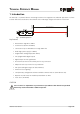
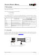
In controlled mode, each operation of a DLS-A(H) is triggered by a command sent from a host system over a
serial line. While a single device can be connected to the host system using the RS232 interface, up to 10
devices can be connected to a single serial RS422 line. The related command set is described in Chapter 8 on
page 19.
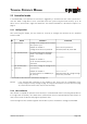
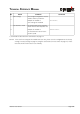
2.2.1 Configuration
After connecting the module, the steps below are necessary to configure the DLS-A(H) for the controlled
interface mode.
No. Action Comment Command
1 Set ID switch Changes of the module ID are activated
after a power cycle.
Example for module 0:
Change the ID Switch to position 0
Set ID switch to position 0
Power OFF; Wait 10s; Power ON
2
Set controlled mode Set the DLS-A(H) to the controlled
mode, if not already in controlled
mode.
Example for module 0:
Set to controlled mode by the stop
command.
s0c<trm>
1)
3
Set communication
parameters
If necessary, change the settings for the
serial interface.
Example for module 0:
Set serial interface to 19200 Baud, 8
Bit, no Parity
s0br+2<trm>
1)
Power OFF; Wait 10s; Change settings
on the host; Power ON
1) Commands are described in 8 Command set on page 19
Remark: If the communication parameters of the module are lost, please reset the configuration to the
factory settings (7 Factory settings on page 18) using the reset button (5.2 Reset switch on page
15). Please note that the ID switch must be reset manually.
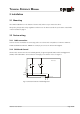
2.2.2 Host software
Host software is required for operation of the DLS-A(H) in controlled mode. When connecting multiple devices
to a single serial line (RS422), strict Master-Slave communication must be implemented (DLS-A(H) operates as
slave). Please consult the Dimetix web page for application notes.
Careful testing of the host software together with the devices prior to installation is strongly recommended.
Distance Laser Sensor Page 7/40