
Technical data

TECHNICAL REFERENCE MANUAL
2 Device setup
We recommend performing the configuration steps in an office before mounting the device, especially if you are
not familiar with the DLS-A(H).
The DLS-A(H) supports two types of operation modes:
• Controlled mode
• Automatic mode
The first decision to be taken is the type of operation mode that will be used to transmit the distance
measurement data. While the controlled mode provides maximum flexibility and accuracy, it is often not suitable
for integration into existing PLCs or analog environments. In such cases the automatic mode might be preferred.
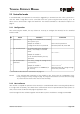
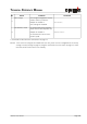
Key controlled mode automatic mode
(with analog output and digital outputs)
Accuracy Maximum measurement accuracy Accuracy depends on signal scaling
(see 8.3.5 Set distance range (sNv) on page 23)
Flexibility Access to full command set Limited
Integration Requires protocol implementation Wiring of AO and DO signals
Connection Connection of up to 10 DLS-A(H)s to a
single RS-422 line.
Point-to-point connection
The following two sections describe the configuration of the DLS-A(H) for the controlled and automatic modes.
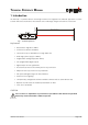
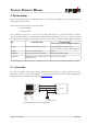
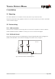
2.1 Connection
To be able to configure the DLS-A(H), it must be powered and connected to a PC. Figure shows the necessary
connections. On the PC, any terminal program can be used to communicate with the module. Additionally, a
configuration utility is available on the web page www.dimetix.com
.
Distance Laser Sensor Page 6/40
Fig. 2 Connection for DLS-A configuration
DLS-A(H)
9 pin
D-Sub
Tx
Gnd
2
5
3
Tx
Rx
2
1
GND
V+
Rx
15 pin
D-Sub
9..30VDC
24..30VDC for DLS-AH
+-
14,15
7,8
Default setting:
Baud:
Bit:
Parity:
Stop:
19200
7
even
1
COM1 or COM2