
Technical data

TECHNICAL REFERENCE MANUAL
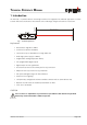
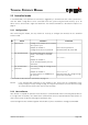
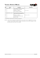
1.1 Product identification
The product is identified by the serial label on the top of the enclosure:
Version Typical Accuracy
1.5mm 3.0mm
Standard version DLS-A 15
Part No.: 500502
DLS-A 30
Part No.: 500501
Extended temperature range DLS-AH 15
Part No.: 500512
DLS-AH 30
Part No.: 500511
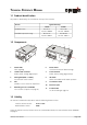
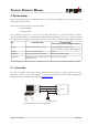
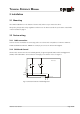
1.2 Components
1 Status LEDs
status signaling
2 15-Pin D-Sub connector
RS422, RS232, analog, digital output
3 Cable gland (M16 x 1.5mm)
for connection cable insertion
4Cab
provides access to electrical components
5 Mounting area for viewfinder
see accessories (Chapter 9 on page 32)
6 Reset switch
resets the DLS-A(H) to default settings
7 Screw terminal
RS422, RS232, analog, digital output
8 ID switch
defines the module ID for RS422 operation
9 Laser beam outlet
10 Receiver optics
11 Product label
see 10.7 Labeling on page 39
1.3 Validity
This manual is valid for DLS-A(H) devices with the following software version:
Interface software version: 0117 or later
Board software version: 0200
To get the software version of the DLS-A use the command described in 8.3.9 Get software version (sNN00N)
on page 25
Distance Laser Sensor Page 4/40
5
8
7
6
10
1
9
1
1
1
5
4
2
3
1
11