
Technical data

TECHNICAL REFERENCE MANUAL
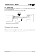
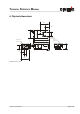
5.5 Connector
5.5.1 D-Sub connector
Pin Designator Description
1 Rx RS232 receive line
2 Tx RS232 send line
3 T- RS422 send line negative
4 T+ RS422 send line positive
5 R- RS422 receive line negative
6 R+ RS422 receive line positive
7PWR
8PWR
DC Power
+ 9V…+30V for DLS-A
+24V…+30V for DLS-AH (Heating option)
9 DO 1 Digital output 1 (Open Drain)
10 DO 2 Digital output 2 (Open Drain)
11 DO E Digital output for error signalization (Open Drain)
12 AGND Analog ground
13 AO Analog output (0/4..20mA)
14 GND Ground line
15 GND Ground line
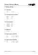
5.5.2 Screw terminal
Pin Designator Description
1 R+ RS422 Receive line positive
2 R- RS422 Receive line negative
3 T+ RS422 Send line positive
4 T- RS422 Send line negative
5 Tx RS232 Transmit line
6 Rx RS232 Receive line
7 AGND Analog ground
8 AO Analog output (0/4..20mA)
9 DO E Digital output for error signalization (Open Drain)
10 DO 2 Digital output 2 (Open Drain)
11 DO 1 Digital output 1 (Open Drain)
12 GND Ground line
13 PWR Power DC
+9V...+30V DLS-A
+24...+30V DLS-AH (Heating option)
Distance Laser Sensor Page 16/40
No.1
1
9
15
8