
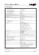
Technical data

TECHNICAL REFERENCE MANUAL
5 Electrical components
5.1 ID switch
This switch is used to set the module ID and can be set from 0 to 9.
5.2 Reset switch
To reset the module to factory settings do the following:
• Switch OFF the power for the module
• Press the reset button and keep it pressed
• Switch on the power for the module
• Keep the reset button pressed until all LEDs on the module are illuminated
• Release the reset button and wait until the green power LED is on
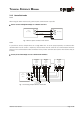
5.3 Digital output
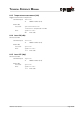
The DLS-A(H) contains two digital outputs for level monitoring (DO 1 and DO 2)
and one digital output for error signalization (DO E). These outputs are open drain
outputs as shown in figure 7 and can drive up to 200mA. In the ON state, the FET
transistor is electroconductive.
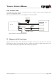
5.4 Analog output
The analog output of the DLS-A(H) is a current source (0..20mA or 4..20mA). It is capable of driving loads up to
500Ω.
The analog output has an accuracy of +/- 1% Full scale.
Distance Laser Sensor Page 15/40
Fig. 7 Open drain output
DOU
T
O
n