
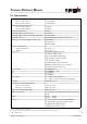
Technical data

TECHNICAL REFERENCE MANUAL
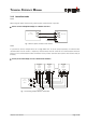
3.2.4 Automatic mode
The analog interface of the DLS-A(H) is isolated from the rest of the device. When using the analog interface,
connect the analog ground (AGND).
Make sure, that the total resistance in the analog path is smaller than 500 Ω.
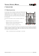
3.3 Alignment of the laser beam
Alignment of the laser beam is often difficult when the target is far away, as the laser spot is not visible. The
DLS-A(H) has an adapter for mounting a telescopic viewfinder that simplifies alignment significantly. Please
refer to chapter 9 Accessories on page 32 for a description of the viewfinder.
Distance Laser Sensor Page 12/40
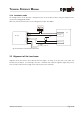
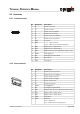
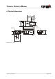
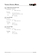
Fig. 6 Connection of an instrument and a PLC
Analog Input
0..20mA
DLS-A(H)
12
14,15
13
Digital Input
24V=
9..30VDC
24..30VDC for DLS-AH
0V
PLC
AO
AGND
DO 1
DO 2
V+
GND
7,8
9
10