
Technical data

TECHNICAL REFERENCE MANUAL
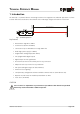
3 Installation
3.1 Mounting
Three M4 threaded holes in the bottom of the DLS-A(H) make it easy to mount the device.
Always obey all applicable safety regulations and never use the device outside the specifications stated under
4 Technical data on page 13
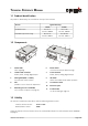
3.2 Device wiring
3.2.1 Cable connection
A ferrite must be mounted to the connecting cable. Use a ferrite with a impedance of 150 Ω to 260 Ω at
25MHz and 640 Ω to 730 Ω
at 100MHz. As example you can use SFC10 from KE Kitagawa.
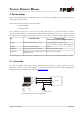
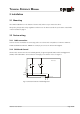
3.2.2 Shield and Ground
The DLS-A(H) contains two electrical isolated grounds, the general ground (GND) and the analog ground
(AGND). GND and AGND is connected to the housing by a RC element. Please see figure 3
Distance Laser Sensor Page 10/40
Fig. 3 Connection between shield and ground
DLS-A(H)
Screw terminal
GND
AGND
15 pin D-Sub
GND
AGND
20nF
1M
10nF
500k