Distance Laser Sensor DLS-A 15 DLS-A 30 DLS-AH 15 DLS-AH 30 Technical Reference Manual V1.06 Please check www.dimetix.
Table of Contents 1 Introduction.......................................................................................................................................................3 1.1 Product identification................................................................................................................................4 1.2 Components.............................................................................................................................................4 1.3 Validity..
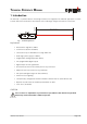
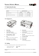
TECHNICAL REFERENCE MANUAL 1 Introduction Measured distance Target Measuring reference The DLS-A(H) is a powerful distance measuring instrument for integration into industrial applications. It allows accurate and contact-less distance measurement over a wide range using the reflection of a laser beam: Fig. 1 Standard application Key features • Measurement range 0.2 to 200 m • Serial interface (RS232 and RS422) • Connection of up to 10 modules on a single RS422 line • Wide range power supply (9.
TECHNICAL REFERENCE MANUAL 1.1 Product identification The product is identified by the serial label on the top of the enclosure: Version Typical Accuracy 1.5mm 3.0mm Standard version DLS-A 15 Part No.: 500502 DLS-A 30 Part No.: 500501 Extended temperature range DLS-AH 15 Part No.: 500512 DLS-AH 30 Part No.: 500511 1.
TECHNICAL REFERENCE MANUAL 1.4 Measurement range The DLS-A(H) is an optical instrument, whose operation is influenced by environmental conditions. Therefore, the measurement range achieved in the application can vary.
TECHNICAL REFERENCE MANUAL 2 Device setup We recommend performing the configuration steps in an office before mounting the device, especially if you are not familiar with the DLS-A(H). The DLS-A(H) supports two types of operation modes: • Controlled mode • Automatic mode The first decision to be taken is the type of operation mode that will be used to transmit the distance measurement data.
TECHNICAL REFERENCE MANUAL 2.2 Controlled mode In controlled mode, each operation of a DLS-A(H) is triggered by a command sent from a host system over a serial line. While a single device can be connected to the host system using the RS232 interface, up to 10 devices can be connected to a single serial RS422 line. The related command set is described in Chapter 8 on page 19. 2.2.
TECHNICAL REFERENCE MANUAL 2.3 Automatic mode The automatic mode is provided for host-less operation of the DLS-A(H). The analog and digitals outputs are updated according the configuration described below as soon as the unit is powered up. Analog Output The analog output is configurable and works with two ranges: – 0..20mA – 4..20mA Digital Outputs Three digital outputs are included in the DLS-A(H). Two are programmable, while the third is used to signal an error state of the device. 2.3.
TECHNICAL REFERENCE MANUAL No. Action Save settings Comment The changed configuration must be saved to make it permanent. 5 Example for module 0: Save settings for module 0 Set automatic mode 6 Command s0s1) Set the DLS-A(H) to the automatic mode with the desired update rate. Example for module 0: Set measurement rate to fastest possible speed.
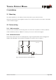
TECHNICAL REFERENCE MANUAL 3 Installation 3.1 Mounting Three M4 threaded holes in the bottom of the DLS-A(H) make it easy to mount the device. Always obey all applicable safety regulations and never use the device outside the specifications stated under 4 Technical data on page 13 3.2 Device wiring 3.2.1 Cable connection A ferrite must be mounted to the connecting cable. Use a ferrite with a impedance of 150 Ω to 260 Ω at 25MHz and 640 Ω to 730 Ω at 100MHz. As example you can use SFC10 from KE Kitagawa.
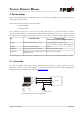
TECHNICAL REFERENCE MANUAL 3.2.3 Controlled mode RS232 When using the RS232 interface only point-to-point communication is possible. ❢ Never connect multiple DLS-A(H)s on a RS232 serial line Host (PC or PLC) Tx 1 Rx Rx 2 Tx DLS-A(H) 9..30VDC 24..30VDC for DLS-AH 7,8 V+ 14,15 0V Fig. 4 Point-to-point connection with RS232 RS422 It is possible to connect multiple devices on a single RS422 line. To ensure proper operation, strict Master-Slave communication must be used.
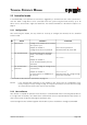
TECHNICAL REFERENCE MANUAL 3.2.4 Automatic mode The analog interface of the DLS-A(H) is isolated from the rest of the device. When using the analog interface, connect the analog ground (AGND). Make sure, that the total resistance in the analog path is smaller than 500 Ω. 13 DLS-A(H) 12 9 10 7,8 14,15 AO Analog Input 0..20mA AGND PLC 24V= DO 1 DO 2 V+ GND Digital Input 9..30VDC 24..30VDC for DLS-AH 0V Fig. 6 Connection of an instrument and a PLC 3.
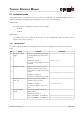
TECHNICAL REFERENCE MANUAL 4 Technical data 4.1 Measuring accuracy The measuring accuracy corresponds to the ISO-recommendation ISO/R 1938-1971 with a statistical confidence level of 95.4% (i.e. ± twice the standard deviation σ, refer to diagram on the right). The typical measuring accuracy relates to average conditions for measuring. It is ±1.5mm for the DLS-A(H) 15 and ± 3.0mm for the DLS-A(H) 30 valid in the tracking mode 99.7% 95.
TECHNICAL REFERENCE MANUAL 4.
TECHNICAL REFERENCE MANUAL 5 Electrical components 5.1 ID switch This switch is used to set the module ID and can be set from 0 to 9. 5.2 Reset switch To reset the module to factory settings do the following: • Switch OFF the power for the module • Press the reset button and keep it pressed • Switch on the power for the module • Keep the reset button pressed until all LEDs on the module are illuminated • Release the reset button and wait until the green power LED is on 5.
TECHNICAL REFERENCE MANUAL 5.5 Connector 5.5.
TECHNICAL REFERENCE MANUAL 6 Physical dimensions 88.5 40.0 = = 80.0 = = 38.5 3 x M4 x 5 150.0 M16 x 1.5 152.5 34.2 53.0 10.5 Laser Beam Measuring reference 33.3 17 80.
TECHNICAL REFERENCE MANUAL 7 Factory settings 7.1 Operation Mode: Controlled 7.2 Communication parameters Baud: Data bit: Parity: Stop bit: 19200 7 Even 1 7.3 Analog outputs Min output: Range min: Range max: Error output: 4mA 0m 10m 0mA 7.4 Module ID ID Number: 0 7.5 Digital output 1 (DOUT1) ON: OFF: 2m + 5mm = 2005mm 2m - 5mm = 1995mm 7.
TECHNICAL REFERENCE MANUAL 8 Command set 8.1 General 8.1.1 Command termination All commands for the DLS-A(H) are ASCII based and terminated with . 8.1.2 Module identification N Since the module can be addressed with the ID switch, the ID is represented in the commands by N. On the location of the N insert the Module ID. 8.1.3 Startup sequence After power on the DLS-A does all the initializations and sends a start sequence gN?. On these sequence, the N stands for the Module ID.
TECHNICAL REFERENCE MANUAL 8.2.3 Temperature measurement (sNt) Triggers measurement of temperature. Command input: Return data Successful: Error: sNt N: Module number (0..9) gNt+xxxxxxxx +xxxxxxxx: temperature in 1/10°C gN@Ezzz zzz: Error code 8.2.4 Laser ON (sNo) Switches laser ON. Command input: Return data Successful: Error: sNo N: Module number (0..9) gN? gN@Ezzz zzz: Error code 8.2.5 Laser OFF (sNp) Switches laser OFF.
TECHNICAL REFERENCE MANUAL 8.2.6 Tracking with buffering – Start (sNf) Triggers continuous measurement of the distance with internal buffering in the module (buffer for one measurement). The rate of measurements is defined with the sampling time. If the sampling time is set to zero, the measurements are executed as fast as possible. The last measurement can be read out from the module with the command sNq. The measurements are continued until the 'sNc' command is issued.
TECHNICAL REFERENCE MANUAL 8.3 Configuration commands 8.3.1 Set communication parameter (sNbr) Sets the communication parameters for the serial interface. The new parameters are immediately saved to the Flash Memory and activated after the power ON. Bold = default parameters (first use or after reset) ) Command input: sNbr+y N: Module number (0..
TECHNICAL REFERENCE MANUAL 8.3.3 Set analog output min level (sNvm) This command sets the minimum analog output current level (0 or 4 mA). Command input: sNvm+x N: Module number (0..9) x: Minimum output for analog out 0: Minimum signal is 0 mA 1: Minimum signal is 4 mA Return data: Successful: Error: gNvm? gN@Ezzz zzz: Error code 8.3.4 Set analog output value in error case (sNve) This command sets the analog output current level in mA in case of an error.
TECHNICAL REFERENCE MANUAL 8.3.6 Set digital output levels (sNn) Sets the distance levels at which the digital outputs are switched ON and OFF with a hysteresis. Two different situations are possible: ON level > OFF level DO The ON level of the hysteresis is larger than the OFF level. With an increasing distance, the digital output is switched on (open drain output is closed) when the distance exceeds the ON level.
TECHNICAL REFERENCE MANUAL 8.3.7 Save configuration parameters (sNs) This command saves all configuration parameters, which are set by the commands above. The parameters are written to the Flash Memory. Command input: Return data: Successful: Error: sNs N: Module number (0..9) gNs? gN@Ezzz zzz: Error code 8.3.8 Set configuration parameters to factory default (sNd) This command restores all configuration parameters to their factory default values. The parameters are written to the Flash Memory.
TECHNICAL REFERENCE MANUAL 8.3.10 Get hardware version (sNN01N) Retrieves the hardware version of the DLS-A(H). Command input: Return data Successful: Error: sNN01N N: Module number (0..9) gNN01N+xxxxxxyy xxxxxx: Board number yy: Revision index gN@Ezzz zzz: Error code 8.3.11 Get serial number (sNN02N) Retrieves the serial number of the DLS-A(H). Command input: Return data Successful: Error: sNN02N N: Module number (0..
TECHNICAL REFERENCE MANUAL 8.4 Command set for single module operation (Compatibility) The commands described in this chapter are compatible with commands form the DISTO OEM Module 3.0. These commands only work properly for point-to-point connections of the serial interface from the module to the PC or any other controller. ❢ Never use these commands if more than one module is connected to the RS422 line 8.4.1 RESET command (a) Resets the module, the status LEDs and the digital outputs.
TECHNICAL REFERENCE MANUAL 8.4.5 Tracking (h) Triggers continuous measurement of the distance. The measurements are continued until the next command is issued or until a fault arises. The status LEDs and the digital outputs are updated corresponding to the new measured distance. Command input: Return data Successful: Error: h 31..06+xxxxxxxx 51....+00000000 xxxxxxxx: Distance in 1/10 mm @Ezzz zzz: Error code 8.4.
TECHNICAL REFERENCE MANUAL 8.4.9 Laser OFF (p) Switches laser OFF. Command input: Return data Successful: Error: p ? @Ezzz zzz: Error code 8.4.10 Software version (N00N) Outputs software version at interface. Command input: Return data Successful: Error: N00N 13....+xxxxyyyy xxxx: Board version number yyyy: SW version number @Ezzz zzz: Error code 8.4.11 Hardware version (N01N) Outputs the hardware version at the interface.
TECHNICAL REFERENCE MANUAL 8.4.13 Date of manufacture (N03N) Outputs the date of manufacture at the interface. Command input: Return data Successful: Error: N03N 15....+YYYYMMDD YYYY: year MM: month DD: day @Ezzz zzz: Error code 8.4.14 Set communication parameter (N70N) Sets the communication parameters for the serial interface. ) The new parameters are immediately saved to the Flash Memory and activated after the next startup.
TECHNICAL REFERENCE MANUAL 8.5 Error codes No. Format Meaning 203 @E203 wrong syntax in command, or prohibited command, or prohibited parameter in command entry, or non-valid result 204 @E204 Dimension error 210 @E210 Not in tracking mode, use command sNf to start tracking mode first.
TECHNICAL REFERENCE MANUAL 9 Accessories 9.1 Viewfinder The telescopic viewfinder can be used for easy alignment of the DLS-A(H) for long distances. Part Number Description 500100 Telescopic viewfinder 9.2 Target plates The target plates provide a defined measuring target. Please use the different sides for the distances as stated below: • Front color brown, for measuring distances from 20 m to 200 m • Back color white, for measuring distances from 0.
TECHNICAL REFERENCE MANUAL 9.4 Cables Part Number Description 500200 PC-Connection cable: DLS-A(H) to - 9 pin D-Sub for PC (RS232) - 2 wires for power supply 500201 RS422-Connection cable: DLS-A(H) to - 5 wires for RS422 - 2 wires for power supply 500202 Connection cable for automatic mode: DLS-A(H) to - 2 wires for current output - 5 wires for digital outputs and power supply 9.
TECHNICAL REFERENCE MANUAL 10 Safety instructions The following directions should enable the person responsible for the DLS-A(H), and the user of the instrument, to anticipate and avoid operational hazards. The DLS-A(H) is made to be integrated into technical systems. A basic technical education is therefore essential. This device may only be operated by trained persons. The person responsible for the instrument must ensure that all users understand these directions and adhere to them.
TECHNICAL REFERENCE MANUAL 10.2 Limits to use ) See section ”Technical Data” Environment: Suitable for use in an atmosphere appropriate for permanent human habitation. Cannot be used in an aggressive or explosive environment. 10.3 Areas of responsibility Responsibilities of the manufacturer of the original equipment Dimetix AG, CH-9100 Herisau (Dimetix): Dimetix is responsible for supplying the product, including the Technical Reference Manual and original accessories, in a completely safe condition.
TECHNICAL REFERENCE MANUAL 10.4 Hazards in use Important hazards in use WARNING: The absence of instruction, or the inadequate imparting of instruction, can lead to incorrect or prohibited use, and can give rise to accidents with far-reaching human, material and environmental consequences. Precautions: All users must follow the safety instructions given by the manufacturer and the directions of the person responsible for the instrument.
TECHNICAL REFERENCE MANUAL WARNING: Operate the equipment appropriately in accordance with the regulations in force. Always prevent access to the equipment by unauthorized personnel. CAUTION: Be careful when pointing a telescope towards the sun, because the telescope functions as a magnifying glass and can injure eyes and/or cause damage inside the DLS-A(H). Precautions: Do not point the telescope directly at the sun. 10.
TECHNICAL REFERENCE MANUAL CAUTION: Looking into the laser beam may be hazardous to the eyes. Precautions: Do not look into the laser beam. Make sure the laser is aimed above or below eye level (particularly with fixed installations, in machines, etc.). 10.
TECHNICAL REFERENCE MANUAL 10.7 Labeling LASER RADIATION DO NOT STARE INTO BEAM CLASS 2 LASER PRODUCT 620-690nm 0.95mW max. Class 2 Laser Product Complies with 21CFR 1040.10 and 1040.11 except for deviations pursuant to Laser Notice no.50, dated May 2001, with IEC 60825-1 (2001) and EN 60825-1 (2001) Dimetix AG CH-9100 Herisau WWW.DIMETIX.COM Made in Switzerland DLS-A 30 Type: Part No.: 123456 Serial No.
TECHNICAL REFERENCE MANUAL 10.8 Maintenance The DLS-A(H) is almost maintenance free. The only thing you have to do is cleaning the optical surfaces. CAUTION: Look after the optical surfaces with same care that you would apply to spectacles, cameras and field glasses. 10.9 Service If you need to service the device, please contact Dimetix for instructions. Dimetix AG Degersheimerstr. 14 CH-9100 Herisau Switzerland © Copyright by Dimetix 2004 Tel. + 41–71–383 20 10 Fax + 41–71–383 20 11 Email info@dimetix.