
User manual


ASURO - 32
-
6.8. One motor does not move
6.8.1. Both motors do not move
Check polarity and position of IC3.
6.8.2. The left motor does not move or only in one direction
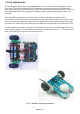
In this case the complete motor bridge, consisting of transistors T1, T2, T3, T4 (did you insert the
correct transistors at the correct positions?), the diodes D1, D2, D3, D4 (polarity!) and resistors
R1, R2, R3, R4.
BC327-40 or BC328-40, BC337-40 or BC338-40, BC327-40 or BC328-40, BC337-40 or
BC338-40
1KΩ (brown , black, red, gold)
6.8.2. The right motor does not move or only in one direction
In this case the complete motor bridge, consisting of transistors T5, T6, T7, T8 (did you insert the
correct transistors at the correct positions?), the diodes D5, D6, D7, D8 (polarity!) and resistors
R5, R6, R7, R8
BC327-40 or BC328-40, BC337-40 or BC338-40, BC327-40 or BC328-40, BC337-40 or
BC338-40
1KΩ (brown , black, red, gold)
6.8.4. One motor turns in the reversed direction
Check the cables, which connect the motor to the system. These connections should be
interchanged.
6.9. IR-interface
6.9.1. ASURO does not send symbols
Check polarity of IR-Diode D10.
Check resistor R16 220Ω (red, red, brown, gold)
6.9.2. ASURO does not receive symbols
You will need a line of sight between IR-Transceiver and ASURO (at a distance of max. 50 cm)
and the IR-Transceiver must be checked and OK (see chapter
6.1).
Check position and polarity of C2.
Check resistor R17 and C2.
220Ω (red,red, brown, gold)
100nF (imprint 104)
If you have not found the error yet, please remind the soldering of IC2. This component is sensitive
to overheating and may have been damaged while soldering. In this case replace the component
by a new IC (SFH 5110-36). When the transfer of data between PC and ASURO is malfunctioning
again and again, re-adjust trimmer TR1 in the transceiver.
Electronics