
User manual


ASURO - 31
-
6.6.2. The display reacts as if switches have been interchanged
Resistors to the switches have been interchanged
Check R24, R25, R26, R27, R28, R29, R30, R32 as well!
1KΩ (brown, black, black, brown, brown)
2KΩ (red, black, black, brown, brown)
8,2KΩ (grey, red, black, brown, brown)
16KΩ (brown, blue, black, red , brown)
33KΩ (orange, orange, black, red, brown)
68KΩ (blue, grey, black, red, brown)
6.6.3. Things still do not work well
Check R23, R24. Check R12, R13 and check C7 as well!
1MΩ (brown , black, green, gold)
1KΩ (brown, black, black, brown, brown)
12KΩ, (brown, red, black, red, brown)
10KΩ, (brown, black, black, red, brown)
220µF/10V
6.7. The re ected light sensor (the odometer) does not work
6.7.1. None of the re ected light sensors (odometer) is working
Check resistor R22!
470Ω (yellow, violet, brown, orange)
Check rotation of D13 and D14. D13 and D14 are rose- or grey-colored bipoled components with a
small spot at one side. The spot must point to the outside of the PCB.
6.7.2. The left re ected light sensor (odometer) does not work
Check resistor R18!
4,7KΩ (yellow, violet, red, gold)
Check rotation of T11, which is a transparent or black bipoled component with a small spot at one
side. The spot must point to the outside of the PCB.
6.7.3. The right re ected light sensor (odometer) does not work
Check resistor R20!
4,7KΩ (yellow, violet, red, gold)
Check rotation of T12, which is a transparent or black bipoled component with a small spot at one
side. The spot must point to the outside of the PCB.
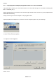
You may check the sensor signal at Pin24 respectively Pin23 after removing the processor.
(dark ≈ VCC, light ≈ 0V)
Electronics