
User manual


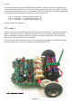
ASURO - 30
-
6.4.3. Left back-LED D15 does not work
Check polarisation of LED D15.
Check resistors R19, R18.
1KΩ (brown, black, red, gold)
4,7KΩ (yellow, violet, red, gold)
A simple check may be done the following way: remove the processor (IC1) and connect by wire
Pin7 (VCC) and Pin24 (left back-LED will be activated red). If this test is succesful, (1) either the
processor may be defective, or (2) a track of the PCB may be broken / interrupted.
6.4.4. Right back-LED D16 does not work
Check polarisation of LED D16.
Check resistors R21, R20.
1kΩ (brown, black, red, gold)
4,7kΩ (yellow, violet, red, gold)
A simple check may be done the following way: remove the processor (IC1) and connect by wire
Pin7 (VCC) and Pin23 (right back-LED will be activated red). If this test is succesful, (1) either the
processor may be defective, or (2) a track of the PCB may be broken / interrupted.
6.5. Linetracer sensor (T9, T10) does not work
Check polarisation of T9, T10.
Check resistors R14, R15.
20KΩ (red, black, orange, gold)
Check, if R15, R23 and R28 have not been inserted in a wrong position!
Check the sensor signal at Pin25 respectively Pin26 with a multimeter after removing the
processor (dark ≈ 0V, light ≈ VCC).
6.6. A switch does not work
6.6.1. Obviously a combination of switches has been activated
Check R12 and R13
12KΩ, (brown,red,black,red,brown)
10KΩ, (brown,black,black,red,brown)
Check R24, R25, R26, R27, R28, R29, R30, R32 as well!
1KΩ (brown, black, black, brown, brown)
2KΩ (red, black, black, brown, brown)
8,2KΩ (grey, red, black, brown, brown)
16KΩ (brown, blue, black, red , brown)
33KΩ (orange, orange, black, red, brown)
68KΩ (blue, grey, black, red, brown)
2KΩ (red, black, black, brown, brown)
Electronics