
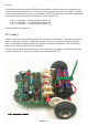
User manual


ASURO - 29
-
6.3.2. Only one of both back-LEDs is glowing
Did you insert the diodes (rose- or red-colored), D13 (left) ,D14 (right), and the phototransistors
(transparent or black case) T11 (left), T12 (right) at the correct position and with the correct
polarisation?
Check the value for resistors R18, R19 (left) and R20, R21 (right)?
4,7KΩ (yellow, violet, red, gold)
1KΩ (brown, black, red, gold)
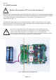
Have these parts been inserted at the correct position? (check the imprint on the PCB!).
6.3.3. Status-LED (D12) is not activated bicolored after startup
Status-LED is not activated at all -> see 6.4!
Status-LED ickers. Battery voltage is too low. Replace batteries.
If the batteries are fresh, check resistors R12 and R13.
12KΩ (brown,red,black,red,brown)
10KΩ (brown,black,black,red,brown)
6.4. A display element does not work
Has the processor been inserted correctly ? (Polarity!)
6.4.1. Status-LED D12 does not work
Check polarisation of LED D12.
Check resistors R10, R31
470Ω (yellow, violet, brown, gold)
A simple check may be done the following way: remove the processor (IC1) and connect by wire
Pin7 (VCC) and Pin14 (Status-LED will be activated green) respectively Pin4 (Status-LED will be
activated red). If this test is succesful, (1) either the processor may be defective, or (2) a track of
the PCB may be broken / interrupted.
6.4.2. Front-LED D11 does not work
Check polarisation of LED D11.
Check resistor R9
220Ω (red, red, brown, gold)
A simple check may be done the following way: remove the processor (IC1) and connect by wire
Pin7 (VCC) and Pin12 (Front-LED will be activated red). If this test is succesful, (1) either the
processor may be defective, or (2) a track of the PCB may be broken / interrupted.
Electronics