
User manual


ASURO - 21
-
5. Preparation for operation
After completing the assembly we will start moving the robot. But rst we will have to nd and
eliminate the errors we could have made in the previous phase, without destroying any parts.
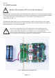
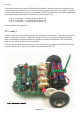
5.1. RS232-Infrared-Transceiver
The following operational check is limited to the RS232-Infrared-Tranceiver (Fig. 4.8).
First of all the IR-Transceiver must be checked, as it will be needed for the next step: the selftest
of the system. For this test connect the IR-Transceiver to a free serial interface of your PC with the
supplied 9-pole serial extension cable and start the Windows terminal program “Hyperterminal” (or
for a Linux-system eg. “Minicom”). Normally you will nd this program in Windows in the category
Addons --> Communication --> Hyperterminal. If the program is not available, you can install it
from the Windows-CD.
After starting the Hyperterminal program you will be asked to de ne a name for the connection.
You may choose ASURO or any other symbol. In the next window you choose “connect by”
and the COM-interface by which the transceiver has been connected in the previous step.
Then press “OK” and choose the following settings:
• Bits pro Second: 2400
• Databits: 8
• Parity: none
• Stopbits: 1
• Flowcontrol: none
Press “OK” again for con rmation
Hold the IR-Transceiver at the distance of 10 cm over a white sheet of paper. The component side
must be directed towards the paper sheet.
Press a few keys at your computer terminal.
The terminal programm normally should display the key-symbols. The IR-Transceiver transmits
the key-symbols by IR-Diode (D5), the transmitted signal re ects at the paper surface and is send
back to receiver-IC (IC2), from which it is being returned to the computer. If no symbols or wrong
symbols are being displayed you may carefully turn the trimmer between its extreme left and right
positions. Use a miniature screwdriver and strike a few keys at each position of the trimmer until
the correct symbols are displayed.
If you do not have any success in this procedure, we do have a problem with the circuit, which
should be solved (see paragraph 6.1).
Just to be sure you should remove the IR-Transceiver after this test and hit a few keys. This time
the display is now expected to show no symbols any more.
Electronics
Fig. 4.8. RS-232 IR-Transceiver