
User manual


ASURO - 20
-
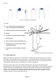
4.4. Attachment of the motors
After completing the insertion of the parts on the ASURO-PCB, we must supply the motors with
cabling and attach these parts temporarely for some tests.
To supply electrical energy to the motor, we need 70 mm red and black wire for each terminal.
These four wires for two motors have to be stripped at both ends for around 4 mm. The ends
of the wires have to be twisted and pre-soldered with some solder. Any surplus parts of solder
attached at the end of the wires may be cut off with a diagonal cutter. By soldering, we attach the
red wire to the motor terminal, marked with a dot or a plus-sign. The black wire will be attached to
the other terminal.
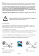
The wiring for the motors may be twisted (not necessary, but it will diminish sensitivity for
electromagnetic disturbances and it looks much better...).
The red wire of the motor on the left side must be soldered into the “ML+”-port, the black wire into
the “ML-”-port, the red wire of the motor on the right side must be soldered into the “MR+”-port, the
black wire into the “MR-”-port.
Next we have to attach the motors temporarily to the PCB by cable-tiers. Use two holes to insert
the supplied cable-tiers. In the rst phase it will be suf cient to attach the two inner cable-tiers only.
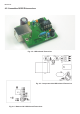
4.5. Power supply
If ASURO is to be equipped and operated with batteries, you must open Jumper JP1
at any rate!
If you decide to use rechargeable devices, the jumper has to be closed.
Reverse placement of power cells with a closed jumper will destroy electronic parts!
Solder the red wire of the battery-holder into the “
BAT+”, and the black wire
into the “
BAT-“
terminal. Check and be sure the ON/OFF-switch is in the OFF-position. Place the four power
cells, correctly polarised, into the
battery-compartment. Right now or after completing all tests,
the
battery-compartment must be attached to the PCB by inserting the larger cable-tie in the PCB-
hole.
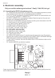
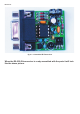
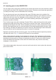
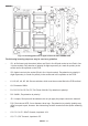
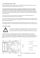
Electronics
Fig. 4.7. Top and bottom view of the PCB