
User manual


ASURO - 19
-
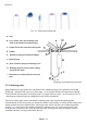
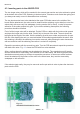
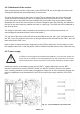
Three more parts will be needed (which will be used to follow a line), but they will be placed at the
bottom side of the PCB and have to soldered from the upper side
(see g.
4.5
):
• T9, T10: SFH300, Phototransistor 5 mm; Pay attention to polarity! These components have
to be placed at some distance from the PCB.
• D11: LED 5 mm red, red or reddisch case; Pay attention to polarity! (short leg must be
inserted at the mark)!
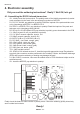
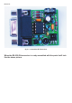
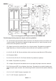
Fig. 4.6 gives an overview of the PCB with all parts inserted up to this phase in top view and in
bottom view.
That’s all! We will need no other electronic components.
In the next steps we will place electromechanical components and mechanical parts.
Fig. 4.6.: ASURO top side and bottom side, completely equipped
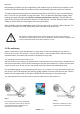
Fig. 4.5.:
Inserting parts at the bottom side of
the ASURO-PCB
Electronics